2203M4JE-MY-iS2-N_2017.04.
Chapter 7 Related Documents
Screw Compressor i-series 7.1 Tightening Angles for Lock Nuts
7-1
Chapter 7 Related Documents
7.1 Tightening Angles for Lock Nuts
When tightening a lock nut, if it is difficult to use a torque wrench, manage the tightening torque of the
lock nut controlling the tightening angle range as explained below.
Tightening Angle Range of Lock Nuts for Rotor
a) After tightening the lock nut by hand, further tighten the lock nut by using a lock nut wrench until the
rotor starts to turn. Take care not to over-tighten.
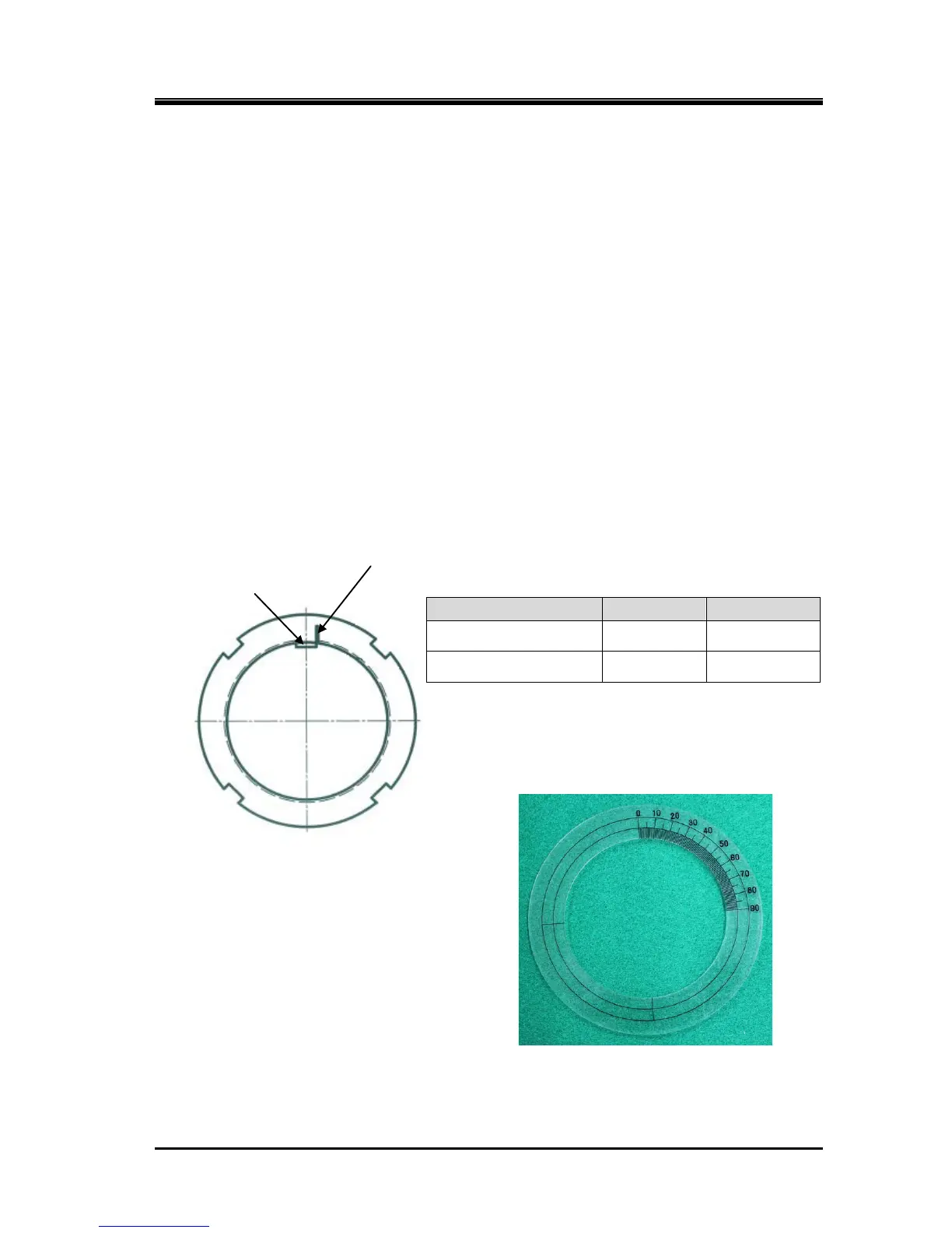
b) Put a mark on the lock nut at the right side edge of the rotor groove where the stopper tongue of
the lock washer fits in, as shown in Figure 7-1.
c) From this marking position, tighten the lock nut in such a way that rotation can be stopped within
the tightening angle range shown in Table 7-1 (i125*/i160*: 30° to 40°(first time tightening), 20° to
30°(second time tightening) for both [39-1] and [39-2]). When measuring the angle, use an angle
gauge which is set to the diameter of rotor shaft.
Table 7-1 Tightening Angles Specified for
Lock Nuts of Rotor
First time tightening i125*, i160* 30° to 40°
Second time tightening i125*, i160* 20° to 30°
* When tightening lock nut, tightening start position differs
between the first time tightening and the tightening for the
second time or after. Therefore, angle ranges are specified
also for the second time tightening.
Figure 7-1
Position where Mark is Put
Photo 041 Angle Gauge (example)
 Loading...

