2203M4JE-MY-iS2-N_2017.04.
Chapter 5 Maintenance and Inspection
Screw Compressor i-series
5.4 Disassembly and Inspection
5-15
5.4.3 Balance Piston
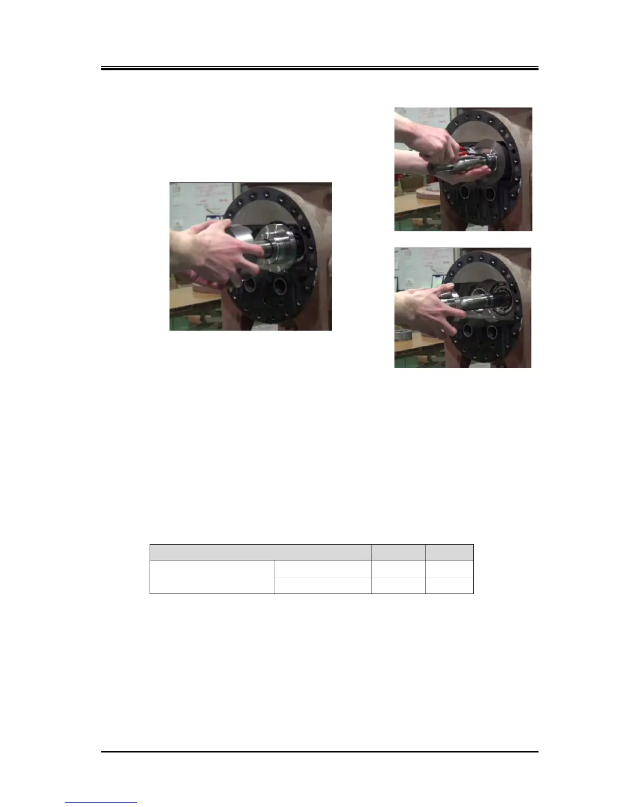
5.4.3.1 Disassembly
The balance piston sleeve [33] and the balance piston [30] can
be removed just by removing the snap ring [32].
Photo 008 Removing the Snap Ring
Photo 009 Removing the Balance Piston Sleeve
Photo 010
Removing the Balance Piston
5.4.3.2 Inspection
a) If there are defects such as extreme wear, galling or chipping on the outer circumference of the
balance piston or on the inner circumference of the balance piston sleeve, replace the defective
component with a new one.
b) Measure the large and small outer diameters of the balance piston at four locations each.
If either of the maximum values indicates that the part is worn down to or beyond the replacement
criteria shown in Table 5-9, the part should be replaced with a new one.
When replacing with new ones replace the balance piston and balance piston sleeve in a set.
Table 5-9 Balance Piston Replacement Criteria
5.4.4 End Cover
a) Remove two hexagon socket head cap screws (i125* [2-2], i160* [2]) symmetrically, and insert stud
bolts. In the case of i160* , attach lifting tools to the end cover before proceeding to the next step.
b) Pull out remaining bolts, and remove the end cover [22]. At this moment, lubricating oil remaining
inside the end cover will flow out. Prepare a container to catch oil.
Balance Piston diameter
(mm)
Large diameter 112.89 134.85