2205Q2JE-HO-S6-N_2020.01.
Chapter 4 Compressor and Package Unit Operation
SCV-series Screw Compressor 4.1 Adjustment of Vi
4-2
b) From the table 4-1 “Number of Turns of Vi Adjusting Rod for Individual Models”, determine how
many turns the adjusting rod [444] should be rotated in order to set to the port selected in Step a)
above.
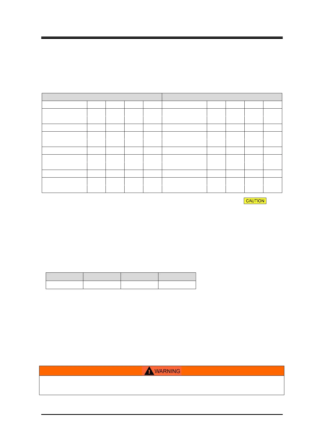
Table 4-1 Number of Turns of Vi Adjusting Rod for Individual Models
(The unit of "Displacement distance" is "mm".)
- 160VL 160VM 160VS - 160VL 160VM 160VS
Displacement distance
- 27 23 18 Displacement distance
- 55 45 37
Number of turns of rod - 10.8 9.2 7.2 Number of turns of rod - 22 18 14.8
- 200VL 200VM 200VS - 200VL 200VM 200VS
Displacement distance
- 34 28 23 Displacement distance
- 69 57 46
Number of turns of rod - 9.7 8.0 6.6 Number of turns of rod - 19.7 16.3 13.1
250VLL 250VL 259VM 250VS 250VLL 250VL 250VM 250VS
Displacement distance
52 43 36.5 29 Displacement distance
-
-
87 72.5 58
Number of turns of rod 13 10.8 9.1 7.3 Number of turns of rod 21.8 18.1 14.5
- 320VL 320VM 320VS - 320VL 320VM 320VS
Displacement distance
- 47 50 59 Displacement distance
- 105 98 98
Number of turns of rod - 10 11 13 Number of turns of rod - 23 21.5 21.5
Note 1: Prior consultation to MAYEKAWA is necessary prerequisite as mentioned in in the
previous page when the port is changed from H port to L port.
Note 2: The travel distance and the rotation number of "From H port to M port" on 320V* have different
tendency of change compared with those of other types. The reason can be found in design
difference of variable Vi auxiliary slide valve.
Note 3:
If the evaporating temperature of your system exceeds 0 °C under the L port condition, select a
grooved slide valve for the compressor.
In addition, note that grooved slide valve is available to even less than 0 °C evaporating
temperature under the L port condition.
Table 4-2 Screw Thread Specifications of Vi Adjusting Rod
Number of turns x Pitch (mm) = Displacement distance of variable Vi auxiliary slide valve
c) If Vi settings are the initial settings before commissioning, set the position of the slide valve at the
no load point, that indicates 0 % in unloader indicator, by driving the oil pump alone after adjusting
the position 0 % to 100 % of the unloader indicator pointer.
If Vi adjusting work is conducted as a change during usual operation, stop the compressor
operation after slide valve reaches 0 % position.
d) Shut off the electric main power source and control power source of the package unit.
In addition use lockout/tagout to prevent power from being reconnected accidentally during the Vi
setting operation.
Take care to the electric shock accident at the time of conducting the electric power
ON/OFF.

 Loading...

