2205Q2JE-HO-S6-N_2020.01.
Chapter 5 Maintenance and Inspection
SCV-series Screw Compressor 5.4 Disassembly and Inspection
5-24
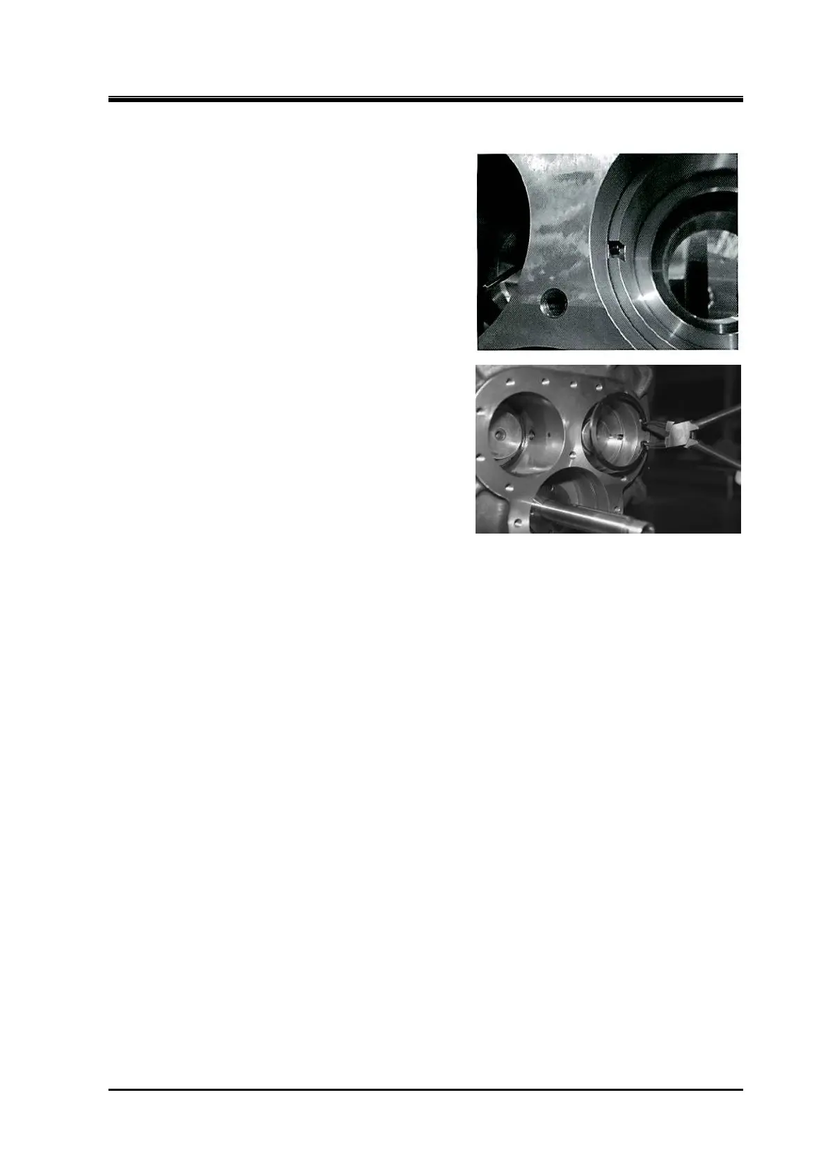
With the balance piston sleeve [33] locked using the
Type 1 method, the sleeve has a notch using which it
is locked by screwing two hexagon socket head cap
screws into a threaded hole, one from the notch side
(M rotor side) and the other from the opposing side (F
rotor side).
To undo the lock of the sleeve, either remove the M
rotor side screw or loosen the F rotor side screw and
screw in the M rotor side screw.
With the balance piston sleeve locked by the Type 2
method, simply remove the stop ring of the sleeve to
undo its locking.
d) Remove the snap ring [37] that secures the balance
piston sleeve by using internal snap ring pliers.
Since the snap ring is pushed out by the inner O-ring
[35], it can be removed easily by pushing gently.
e)
Pull out the balance piston sleeve. The sleeve is loose
fitted, so it can be removed easily.
f) Remove the O-ring [35] and O-ring spacer [36] behind
the sleeve.
5.4.5.2 Inspection
While you will be able to find some trace of wear on the inside surface of the balance piston sleeve,
such wear is not abnormal as it is caused because the clearance between the balance piston and the
sleeve is narrower than the clearance between the rotor shaft and the bearing.
Because enough clearance is given to the outside of balance piston sleeve in order not to apply the
bearing load to the balance piston, no further development of the wear is expected.
However, you should still carefully check the condition because when the side bearing is significantly
worn, the balance piston may also be worn.
Make sure to replace the O-ring [35] with a new one.
By its elasticity, the O-ring work to center the clearance round the periphery of the balance piston
sleeve on the center of the balance piston.