2205Q2JE-HO-S6-N_2020.01.
Chapter 5 Maintenance and Inspection
SCV-series Screw Compressor 5.3 Compressor Disassembly Preparation
5-11
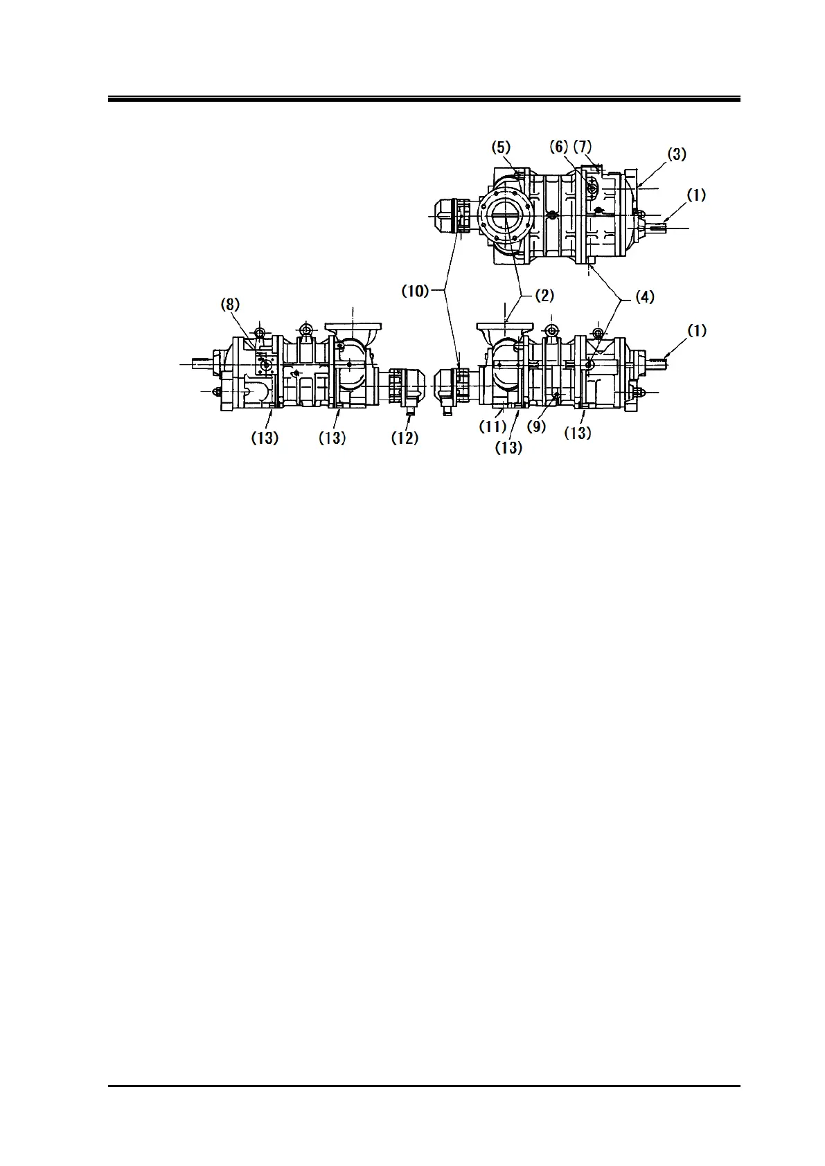
When removing the compressor from the
mounting base frame, the following parts
must be disconnected beforehand in numeric
order of Figure 5-1:
Figure 5-1 Disconnecting Parts
(1) Coupling to connect the compressor to the driving machine;
(2) Suction piping of the compressor.
If the suction strainer is directly connected to the compressor, also remove the strainer;
(3) Discharge piping of the compressor;
(4) Oil supply piping to the compressor (Journal oil inlet port);
(5) Oil supply piping to the side bearing of compressor F rotor side;
(6) Liquid injection (Aquamizer) 1 piping to the compressor;
(7) Liquid injection (Aquamizer) 2 piping to the compressor;
(8) Economizer (Electromizer) piping to the compressor
(9) Oil injection piping to the compressor
(10) Oil piping connection 2 for the capacity control (unload)
(11) Oil piping connection 1 for the capacity control (load)
(12) Electric wiring for capacity control operation (In some cases, the unloader indicator assembly may
be removed without removing the wiring. Refer to Section 5.5.1.1 in this chapter.);
(13) Compressor mounting bolts (foot bolts); and
After performing work of (1) to (13), the openings of the flanges and screwed connections on the
compressor should be prevented from entering foreign matters inside the compressor, by using cover
flanges and plugs.