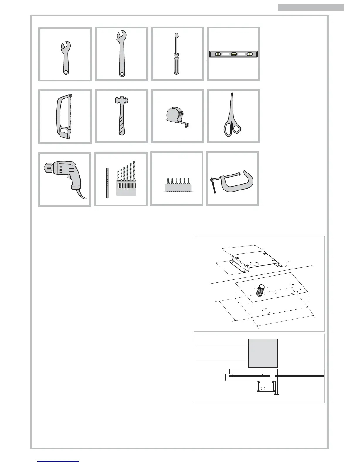
Fig. 2
55/60 mm
20/30 mm
Fig. 3
260+ 50 mm
177+ 50 mm
260
177
32
4
3.4 PRELIMINARY INSTALLATION WORK
AND MASONRY FOR ANCHOR PLATE
Identify approximately the place of each component and
proceed as follows:
a) Dig the foundation pit for the gear motor whilst considering
the anchor plate dimensions. Give an extra 5cm area extra
on each side. Pay attention to measurements shown in Fig.2.
b) Provide one or more ducts for the electrical cables so that
they can easily go through the purpose fabricated hole in
the gear motors anchor plate. Pay attention to the plate’s
orientation: hole for cables routing on the side opposite the
gate (see Fig. 2).
c) Set concrete into the pit. Ensure this is level and smooth out
the surface. Wait for the concrete to get solidify (this may
take a few days).
d) Insert the cables ducting to the hole in the anchor plate and
fix the plate to the concrete using suitable plugs.
e) Cut the cable ducts about 3cm above the anchor plate
level and route the cables for accessories and electrical
mains wiring as shown in Fig. 3 diagram. Ensure the cables
are at least 30-50cm out from the ducting to allow easy
wiring to the control panel.
3.3 TOOLS NEEDED
ENGLISH