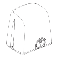
Fig. 13 Fig. 14
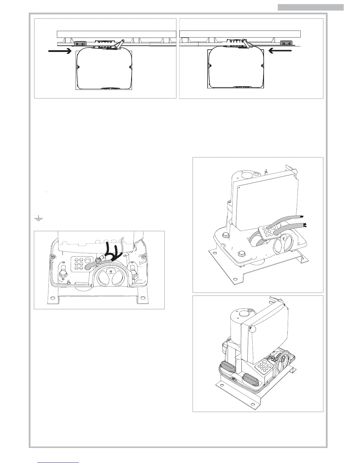
Fig. 16
Fig. 17
Fig. 18
8
3.4 PRELIMINARY INSTALLATION WORK
AND MASONRY FOR ANCHOR PLATE
Identify approximately the place of each component and
proceed as follows:
a) Dig the foundation pit for the gear motor whilst considering
the anchor plate dimensions. Give an extra 5cm area extra
on each side. Pay attention to measurements shown in Fig.2.
b) Provide one or more ducts for the electrical cables so that
they can easily go through the purpose fabricated hole in
the gear motors anchor plate. Pay attention to the plate’s
orientation: hole for cables routing on the side opposite the
gate (see Fig. 2).
c) Set concrete into the pit. Ensure this is level and smooth out
the surface. Wait for the concrete to get solidify (this may
take a few days).
d) Insert the cables ducting to the hole in the anchor plate and
fix the plate to the concrete using suitable plugs.
e) Cut the cable ducts about 3cm above the anchor plate
level and route the cables for accessories and electrical
mains wiring as shown in Fig. 3 diagram. Ensure the cables
are at least 30-50cm out from the ducting to allow easy
wiring to the control panel.
4. ELECTRICAL WIRING
Insert the electrical cables into the control panel’s case by
piercing the rubber membrane and place the cable grommet
in its purpose fabricated seat on the motor’s base (Fig. 16).
Terminate the cable of the main supply with the provided
cable block (Fig. 17).
Follow the control panel’s instruction manual to proceed with
the correct cable wiring. Wire all cables for the earth system to
the provided lug and fix onto the motor base point marked with
symbol.
5. START-UP
Power the system and proceed with a careful checking of the
gear motor working and of all the accessories and safety
devices connected to the system.
In particular make sure that the electric limit-switch is always
activated in opening and closing before the gate reaches its
mechanical stops. Place the two slot-covers on the M10
screws. Lift the motor cover down and close it with the two side
screws.
Hand over this instructions manual to the end user and demon-
strate the correct use of the automation and how to release
the motor for manual operation of the gate in the event of
power cuts.
Once the assembling of the limit brackets to rack is completed, open and close the gate manually to check that the
brackets always activate the limit-switch system before the gate reach its mechanical stops. This checking is important
to preserve the correct working of the automation and continued good mechanical condition of the gate.
NB. Tagliare eventuali eccedenze di cremagliera.
Click!
Click!
ENGLISH
RIGHT motor OPENING limit-switch
LEFT motor CLOSING limit-switch