RC4 decoder V2.0. - October 2017 © MYLAPS rights reserved 13
4.5. The decoder
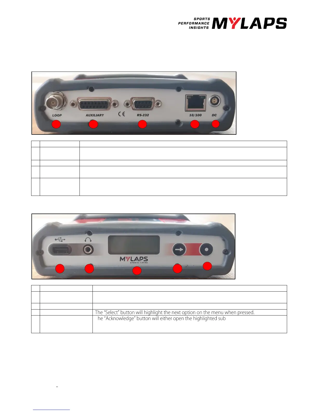
Back side
Connect the supplied 75 Ohm double-shielded coax cable to the decoder.
The auxiliary port has 3 inputs, photo cell 1, photo cell 2, sync pulse and a control port for a GPS
receiver. For more information on how to connect these devices, see appendix 4.
This port can be used to connect the decoder with the computer through a RS232 cable.
This port can be used to connect the network cable between the decoder and the network
connection port of the computer.
Connect the supplied VDC adapter to the decoder and mains. It is recommended to connect the
VDC adapter to mains through a UPS (Uninterruptable Power Supply) to avoid any interruption of
power supply to the decoder.
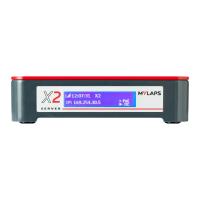
A beep will sound for every passing transponder, which provides an easy check for proper
operation of the decoder and the transponders on the track.
Here you find the menu for setting up your decoder.
T -menu or select the
highlighted option, depending on the situation.