RC4 decoder V2.0. - October 2017 © MYLAPS rights reserved 17
5. Appendix Auxiliary connections
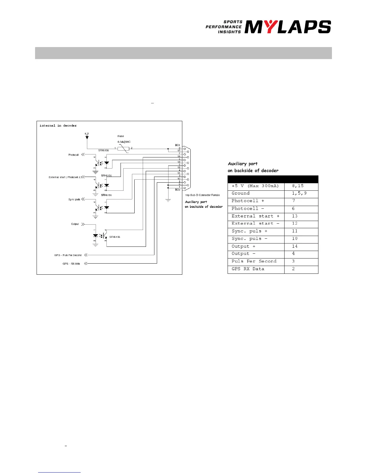
The MYLAPS decoder is equipped with an auxiliary port (15 pin sub D-connector). The auxiliary port has 3 inputs, photo cell 1,
photo cell 2, sync pulse and a control port for a GPS receiver. All inputs can be triggered by a 5 VDC (5-15 mA) pulse. Figure 1
explains the connection setup. To use a photocell, connect it using the MYLAPS photocell cable or make an appropriate
cable using figure 1 below. Two types of photocells are available, passive and active photocells. They both operate as a
switch; to connect the passive photocells please follow the connection setup in figure 1a and scheme 1b. Active photocell
can be connected directly to the photocell/sync and + input pins.