4
EN
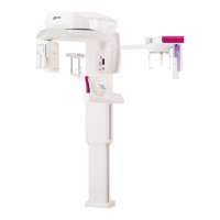
hyperion X5 2D/3D - TECHNICAL MANUAL
DEVICE INSTALLATION
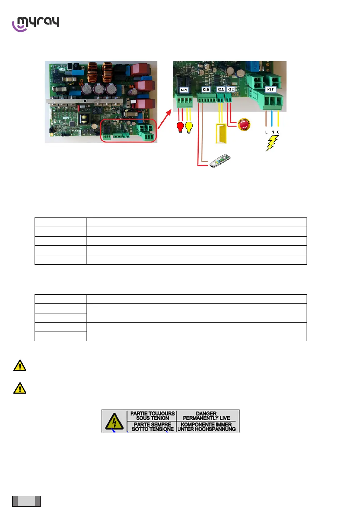
1.3 EXTERNAL CONNECTIONS
K17 - Main supply
K12 - External emergency stop (Optional, short-circuit cable loop installed as factory conguration)
K11 - Door interlock (Optional, short-circuit cable loop installed as factory conguration)
K10 - X-ray button, use any 2-wire switch or the optional button 96609090
CONNECTOR FUNCTION
1 X-Ray Switch – Red wire if using button 96609090
2 X-Ray Switch – Brown wire if using button 96609090
3 Ready LED – only if using button 96609090 (white wire)
4 Emission LED – only if using button 96609090 (blue wire)
K14 - External warning lights, clean contacts, no voltage provided. (Optional) Use lamps up to 240 VAC - max 2 A. Use
a service relay for higher loads.
CONNECTOR FUNCTION
1
“Ready” light
2
3
X-ray emission light
4
WARNING: Comply with the main supply polarity indicated on connector K17
WARNING: The area of input terminal block K17 is always energised, as indicated by the plate below:
Before handling, cut the power by means of the external magneto-thermal switch.
Once the power to the equipment has been cut, wait at least 60 seconds before handling the boards, to allow the ca-
pacitors to discharge.