Component Identificaiton, Calibration and Preventive Maintenance
4.3 CALIBRATION PROCEDURES
All 750/760 Series Monitors are calibrated and tested prior to
shipment.
CAUTION!
When performing Calibration procedures, the user must take
extreme care to avoid contacting fuse or any other portions of
the circuit other than the Calibration controls. Failure to do so
could result in damage to equipment and/or property.
4.3.1 METER MECHANICAL ZERO READING
(752 and 762 analog meters only)
STEP 1 Turn OFF the Monitor’s main AC power and verify that
the meter is indicating a zero (0) reading. If the meter
does not indicate a zero (0) reading, proceed to STEP
2.
STEP 2 Remove the meter’s zero adjustment plug to access
the meter’s Mechanical Zero adjustment screw.
STEP 3 Turn screw until meter indicates a zero (0) reading and
then replace the plug.
NOTE:
If it becomes necessary to replace a faulty meter, see Fig. 4-2
for the meter wire/terminal designations.
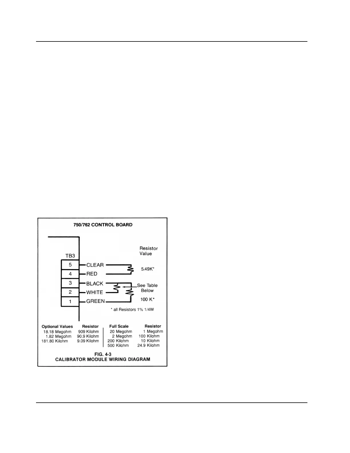
4.3.2 FULL SCALE CALIBRATION PROCEDURES
The Calibration Module is configured for the specific range being
calibrated. See Fig. 4-3 for proper Calibration Module.
4.3.2.1 MODEL 750
STEP 1 Turn “OFF” the Monitor’s main AC power.
STEP 2 Being careful not to excessively strain cable, unfasten
and remove the Monitor’s front panel.
STEP 3 Remove all five (5) wires from Control board terminal
block TB3 (See Fig. 4-1).
STEP 4 By following the wiring diagram in Fig. 4-3, connect the
Calibrator Module’s lead wires to the Control board’s
TB3 terminal connectors.
STEP 5 Turn “ON” the Monitor’s main AC power.
STEP 6 Set the Set Point adjustment knob to a full scale
reading.
STEP 7 Rotate the main calibration trimmer (R8, Fig. 4-1)
counterclockwise until the red light turns on. Now rotate
clockwise slowly and stop when the green light comes
on. Counting turns, rotate counterclockwise and stop
when the red light turns on. Finally, rotate clockwise 1/2
of the turns counted in the last step. This completes the
calibration procedure.
4.3.2.2 MODELS 752, 753 AND 762
Before attempting to calibrate the Model 752 or 762 analog
meter, refer to Section 4.3.1.
STEP 1 Repeat STEPS 1-4 in Section 4.3.2.1.
NOTE:
If equipped with the 3 Cell Input option, place the Cell select
switch to its “CELL 1” setting and remove the five (5) wires from
Cell 1’s terminal block only.
STEP 2 Turn “ON” the main AC power and verify that the 752
and 762 analog meter or 753 digital display is
indicating a full scale reading. (i.e. a 20 megohm
reading on model 752-1 or a 19.99 megohm reading on
model 753-1.)
NOTE:
If the meter indicates an accurate reading, proceed to STEP 4.
If the meter does not indicate the appropriate reading, proceed
to STEP 3.
STEP 3 Turn the Control board’s R8 adjustment screw (See
Fig. 4-1) until the meter displays the appropriate
reading as indicated in STEP 2.
STEP 4 Remove the Calibrator Module’s lead wires and
reconnect the Cell cable wires as shown in Fig. 2-3.
10
 Loading...