Introduction
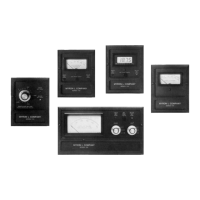
2.4.2 0-5 / 0-10 VDC RECORDER BOARD
STEP 1 Place the user-supplied interface cable and water tight
cable restraint into the enclosure’s appropriate access
hole.
STEP 2 Neatly insert cable wires into the Recorder board’s TB1
plus (+) and minus (-) terminal connectors. (See Fig. 2-5).
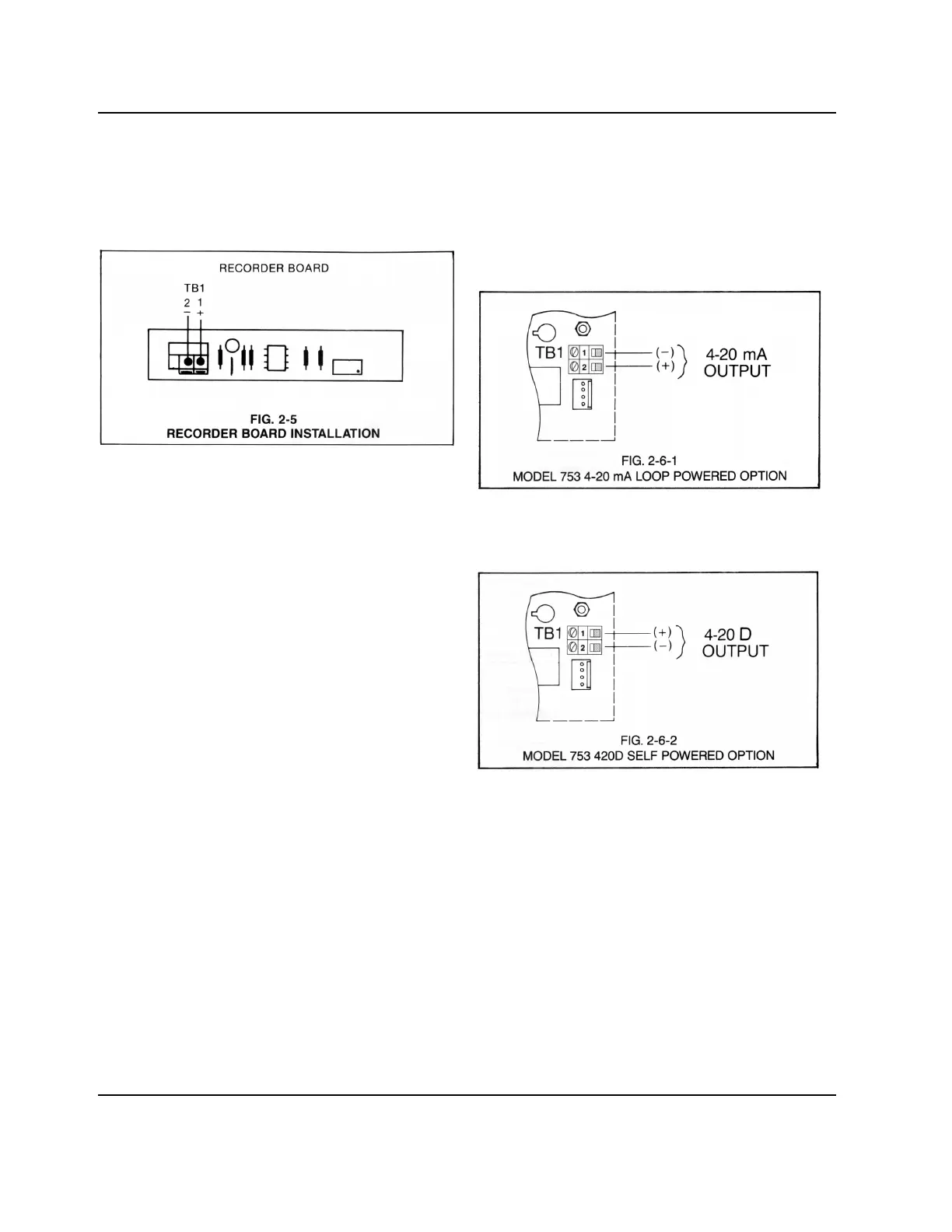
2.4.3 4-20 mA AND 420D TRANSMITTER BOARDS
STEP 1 Place the user supplied cable and watertight cable
restraint into the enclosure’s appropriate access hole.
STEP 2 Neatly insert cable wires into the 753 Panel board plus
(+) and minus (-) TB1 terminal block connectors as
shown in Fig. 2-6-1 or 2-6-2.
STEP 3 See Section 4.3.5 to calibrate the 4-20mA minimum
and maximum current outputs.
6
 Loading...