5
4
rear panel
connections
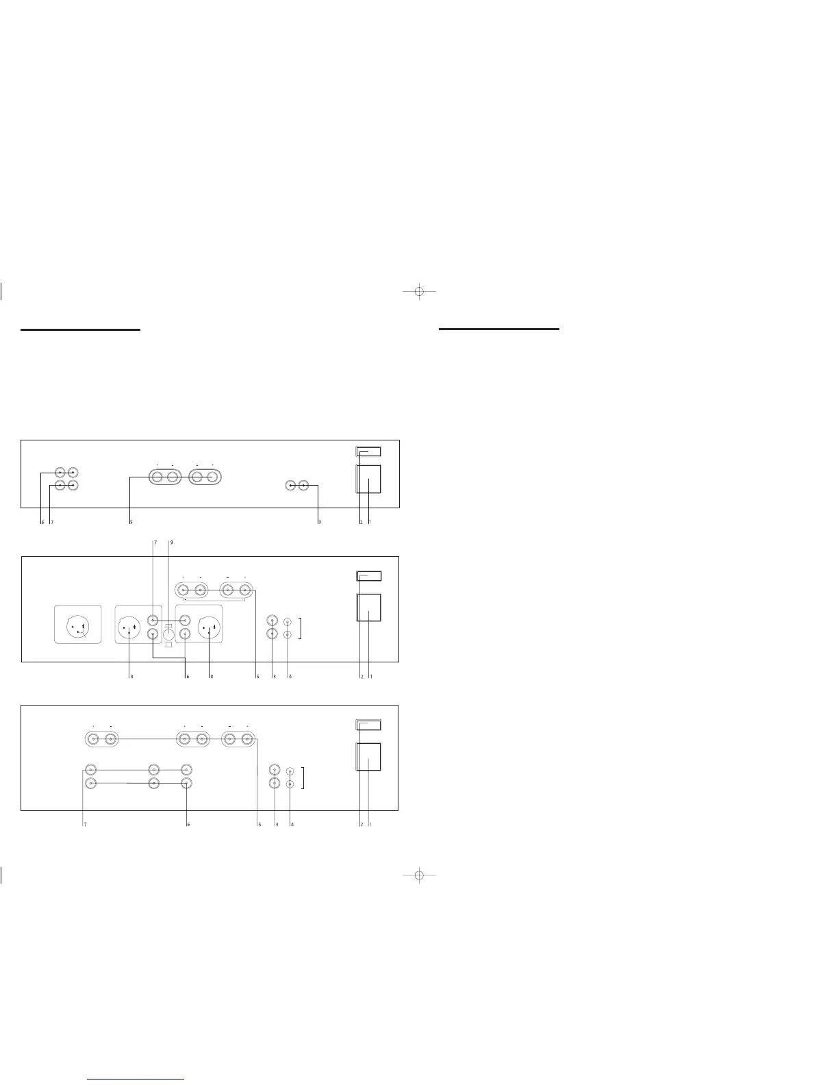
1 Power inlet
Before making any connection, check that the
mains voltage setting printed on the rear
panel is the same as your local mains supply.
Plug the female (socket) end of the power
cord into the power inlet on the rear of the
amplifier. Plug the male (plug) end of the
cord into a“live” wall socket or a suitable
heavy-duty extension cable.
UK version: The mains plug is supplied fitted
with a 5A fuse. It should only be replaced
with a fuse of the same rating (5A) which
complies with BS1362.
2 Power switch
Press one side of this rocker switch (the side
nearer the edge of the rear panel) to switch
amplifier ON and the other side (towards the
speaker terminals) to switch it OFF. When the
POWER switch is in the OFF position all
power is disconnected from the amplifier. In
this condition the amplifier cannot be
powered up from the front panel or the My-
Link (or remote trigger if present). When the
POWER switch is in the ON position (and
the power cord correctly inserted and plugged
in to a live wall socket) the amplifier will
power up in standby mode (see FRONT
PANEL CONTROLS, STANDBY,).
It is recommended that the POWER switch be
turned OFF if the amplifier is not going to be
used for an extended period of time.
3 My-link input/output
When this Power Amplifier is used in a
system with other Myryad M-Series products
all may be joined together via the My-Link.
This will allow the different products to be
remotely controlled via the infra-red receiver
on, for example, an MP 100 Preamplifier. My-
Link offers two benefits. Firstly, only the MP
100 Preamplifier infra-red receiver needs to be
in “line-of-sight” from the remote handset.
Secondly, the My-Link allows remote control
of some Myryad products which do not have
their own infra-red receiver, such as the
Myryad Power Amplifiers.
When joined via the My-Link, the Power
Amplifier will respond to STANDBY and
MUTE operations on the MP 100 Preamplifier
i.e.: if both the MP 100 Preamplifier and the
Power Amplifier are in STANDBY, then
switching the MP 100 Preamplifier out of
standby will also bring the Power Amplifier
out of standby. In this way the MP 100 + MA
240 (or MA 120) can be operated with the
same ease as an integrated amplifier. If Power
Amplifiers are being used in a bi-amp or
tri-amp system all the amplifiers may be
My-Linked so that they can be controlled as
one from the Myryad preamplifier.
NOTE: SWITCHING THE POWER AMPLIFIER
INTO STANDBY WILL NOT SWITCH THE MP 100
PREAMPLIFIER INTO STANDBY.
MA 240 and MA 360 only:
When the My-Link is connected it is
recommended that no connection be made to
the REMOTE TRIGGER input (see below).
4 Remote trigger control input/output
(MA 240 and MA 360 only)
If the MA 240/360 is being used in a system
without a Myryad M-Series preamplifier,
processor or integrated equipped with My-
Link, the REMOTE TRIGGER input may be
used to allow the MA 240/360 to be remotely
switched into or out of STANDBY.
If your preamplifier or processor has a
TRIGGER output which delivers a DC trigger
signal when the unit is switched on (or out
of standby) then it can be linked to the
MA 240/360 to switch the MA 240/360 out
of/into standby also. A lead must be used
which is fitted with a 3.5mm mini-jack plug
to connect to the MA 240/360’s REMOTE
TRIGGER input socket. The lead must be
wired according to the rules below:
• Connector to MA 240/360 REMOTE
TRIGGER input: 3.5mm mini-jack plug
• Jack plug wiring: sleeve negative,
tip positive
• Trigger voltage: DC, 4.5V to 24V
• Nominal loading of MA 240/360
REMOTE TRIGGER input: 2200Ω
• TRIGGER voltage change from 0 to +ve:
Amplifier switched from standby to active
• TRIGGER voltage change from +ve to 0:
Amplifier switched from active to standby
If you are in any doubt about meeting any of
these criteria or preparing a suitable lead, ask
your dealer or installer to handle this for you.
NOTE: IF THE TRIGGER INPUT IS ACTIVE
WHEN THE REAR PANEL POWER SWITCH IS
TURNED ON, THEN THE AMPLIFIER WILL
NOT POWER UP INTO STANDBY MODE AS
USUAL. IT WILL POWER UP IMMEDIATELY
INTO ITS “ACTIVE” STATE – WITH ITS NORMAL
POWER-ON MUTE DELAY (SEE FRONT PANEL
CONTROLS, STANDBY BELOW).
The REMOTE TRIGGER output is wired
directly to the input. Using this output,
further MA 240/360s, or other products, may
be connected from a single trigger source
without needing any special adaptors.
5 Loudspeaker outputs
The loudspeaker outputs are capable of
driving all loudspeakers with impedances in
the range 4Ω to 16Ω (except the MA 240 in
Bridget-Mono – see below).The loudspeaker
terminals are high-current binding-posts,
coded red and black. The terminals on the
left side of the amplifier (viewed from the
front) and marked “L” should be wired to the
left hand loudspeaker. Those on the right,
marked “R”, should be wired to the right
hand loudspeaker.
CAUTION:THE RED TERMINALS ARE MARKED
WITH A HAZARD SYMBOL ~ TO INDICATE
THAT THEY CAN BE LIVE. READ ALL THE
LOUDSPEAKER WIRING INSTRUCTIONS
CAREFULLY. IT IS RECOMMENDED THAT READY-
MADE LEADS BE USED WHERE POSSIBLE.
For correct stereo imaging it is important that
the two loudspeakers are wired “in phase”.
To ensure correct phasing wire the black (-)
terminal on the amplifier to the black or “–”
terminal on the loudspeaker. The red (+)
terminal on the amplifier should be wired to
the red or “+” terminal on the loudspeaker.
The loudspeakers should be positioned
as recommended by the loudspeaker
manufacturer. The two loudspeakers should
always be placed at equal distances from the
main listening position and usually spaced
a similar distance apart. It is generally best
to keep the loudspeakers away from room
corners and many loudspeakers work best
away from all walls.
MA 240 only
When the MA 240 is switched to BRIDGED-
MONO mode, only the red speaker terminals
are used. No connection should be made to
either of the black terminals. For correct
phasing connect the Left hand red (+)
terminal on the amplifier to the red or “+”
terminal on the loudspeaker and connect the
Right hand red (+) terminal on the amplifier
to the black or “–” terminal on the
loudspeaker. Each amplifier and loudspeaker
should be connected in the same way.
CAUTION:WHEN THE MA 240 IS SWITCHED
TO BRIDGED-MONO MODE, EACH AMPLIFIER
DRIVES INTO ONLY HALF THE SPEAKER
IMPEDANCE SO LOUDSPEAKERS RATED AT LESS
THAN 8 Ω IMPEDANCE MUST NOT BE USED.
setting up your
systems
MA 120 Stereo Power Amplifier
MA 240 Stereo Amplifier
MA 360 Three Channel Power Amplifier
 Loading...