07
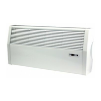
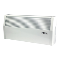
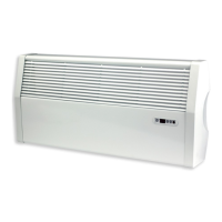
FINESSEFINESSE
06
4.0 Installation 4.0 Installation (cont...)
C 135 205
D 90 163
Height (mm) 300 500
A 160 160 160 160 160 160 160 160 160 160
B 101 203 355 508 660 711 965 1016 1320 1727
Length (mm) 400 500 650 800 950 1000 1250 1300 1600 2000
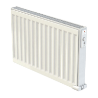
FINESSE Double Panel (refer to figure 2)
STAND ALONE CONNECTION
l
The electrical installation must comply with
local or national regulations.
l
The radiator must be connected to the
electrical supply, using a switched fused
spur with 3mm separation on all poles.
l
If the radiator is installed in a bathroom or
shower room, it must be protected with a
residual current device (RCD) with a rated
residual current not exceeding 30 mA.
l
The radiator should be connected by a
suitable and qualified electrician. Please
refer to the wiring diagram (figure 5) for the
connection of the radiator.
5.0 Maintenance, Repair & Disposal
l
Use only a damp cloth for cleaning and wiping
of the radiator which should be switched off
at this time.
l
When scrapping the radiator, follow the
regulations concerning the disposal of oil.
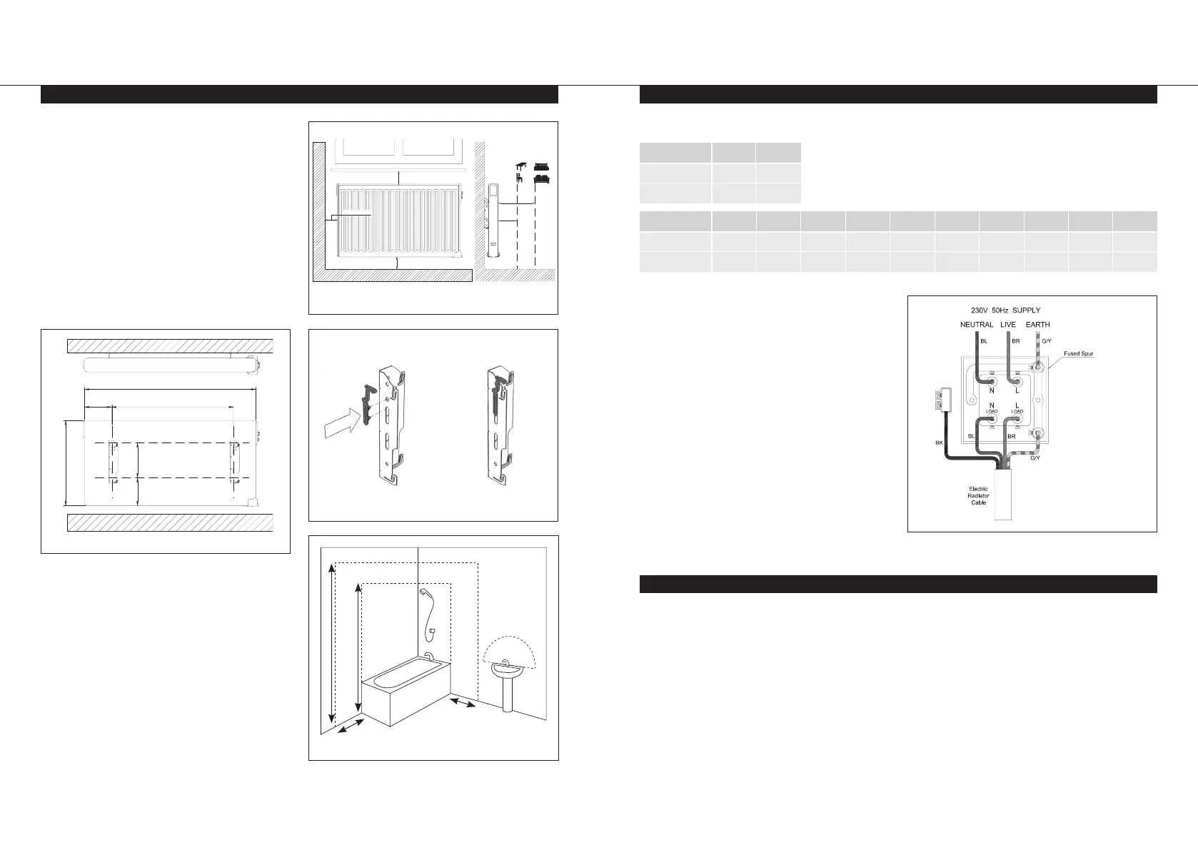
Figure 5.
Wire Colours
BR = Brown
BK = Black (Neutral)
BL = Blue
G/Y = Green/Yellow
POSITIONING
l
The radiator must be positioned horizontally,
the right way up on the wall in order for it to
function correctly. Never switch the radiator
on in any other position as this will damage
the electrical element.
l
The radiator must be positioned according
to the applicable standards and the
minimum distances as specified in figure 1
should be carefully observed.
l
The radiator must not be located
underneath an electric socket.
l
This product is splash resistant with an
IP44 rating. This must be considered when
installing in a location containing a bath or
shower, as defined by BS 7671.
l
The radiator may be positioned in zone 2
(figure 4) of the bathroom, in so far as no
operating controls (button, switch, etc.) are
in reach of persons in the bath or under
the shower.
FIXING
l
Mark out the distance between the brackets
and the positions for the screw holes as
shown in figure 2 and the dimension tables at
the top of page 7, and ensure the safety clips
are used (see figure 3).
A
D
L
B
C
H
FLOOR
Figure 2.
Figure 3.
Figure 1.
Step 1 Step 2
Zone 1 Zone 2
Zone 2
Zone 0
OUTSIDE ZONES
3m
2.25m
0.6m
0.6m
Figure 4.
Safety Clip-on Brackets
Min. 100mm
Min. 100mm
Min. 100mm
Min.
200mm
Min.
100mm
Min. 100mm
Min. 100mm
Min. 100mm