(Revised 2011-03-14)
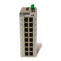
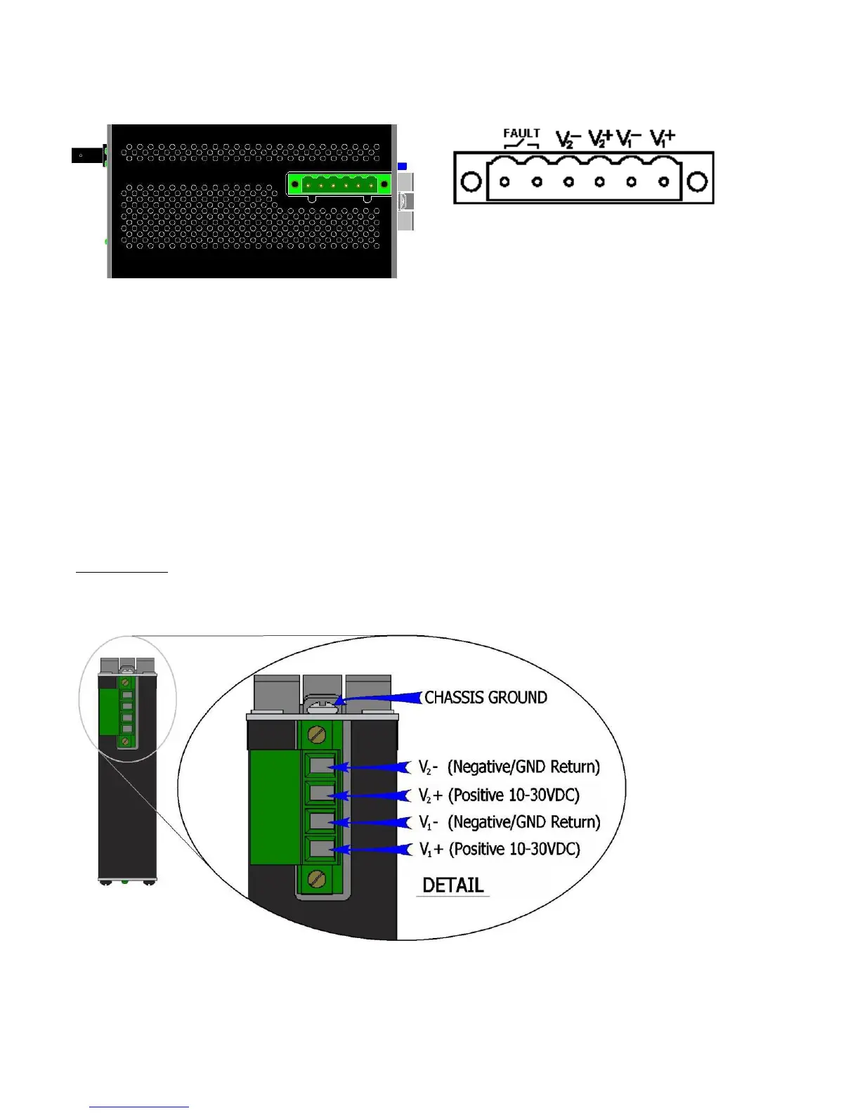
• 110FX2, 111FX3, 112FX4, and 114FX6 Power Connector (Top View)
(must be powered by Class 2 source only)
Unscrew & Remove the DC Voltage Input Plug from the top header. Install the DC Power Cables into the
Plug (observing polarity on unit). Plug the Voltage Input Plug back into the top header. Tightening torque
for the terminal block power plug is 0.22 Nm/0.162 Pound Foot.
All LED’s will flash ON Momentarily. Verify the Power LED stays ON (GREEN).
Note: Either V
1
or V
2
can be connected to power for minimal operation. For redundant power
operation, V
1
and V
2
plugs must be connected to separate DC Voltage sources. Use wire sizes of 16-28
gauge. The power cord should be limited to less than 10 meters in order to ensure optimum
performance.
Recommended 24V DC Power Supplies, similar to:
100-240VAC: N-Tron NTPS-24-1.3, DC 24V/1.3
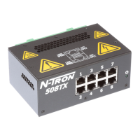
• 105TX-SL (Top View)
Unscrew & Remove the DC Voltage Input Plug from the top header. Install the DC Power Cables into the Plug
(observing polarity on unit). Plug the Voltage Input Plug back into the top header. Tightening torque for the terminal
block power plug is 0.5 Nm/0.368 Pound Foot.
 Loading...