This document is a service manual for the NAD 4225 Stereo Tuner, providing detailed instructions for alignment, troubleshooting, and component location.
Function Description:
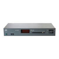
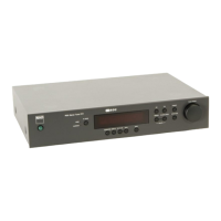
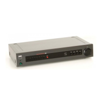
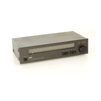
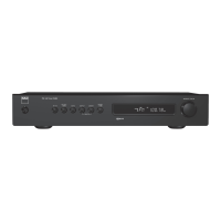
The NAD 4225 is a stereo tuner designed to receive and process FM and AM radio signals. It features a stereo decoder for FM stereo reception and MPX filters to enhance audio quality. The tuner incorporates a synthesizer for precise frequency tuning and an autosearch function for convenience.
Important Technical Specifications:
FM Alignments:
- FM Generator: Requires a generator with less than 0.05% THD.
- Stereo Generator: Requires a generator with less than 0.05% THD and more than 50 dB separation at 1 KHz.
- THD Analyzer: Resolution better than 0.1%.
- Oscilloscope: 5mV or better sensitivity, with X input capability.
- Tuning Voltage (Oscillator):
- At 108 MHz: 20.5V ±0.5V
- At 87.5 MHz: 3V ±0.5V
- Detector Alignments (Final):
- THD (Total Harmonic Distortion): Less than 0.1%.
- Input Level for 3% THD: Typically 1.6 uV to 2.3 uV.
- FM DET PRIMARY (I102): 0V ±50 mV on DMM.
- Autosearch Level:
- DMM reading between P120 and ground should go from 8.5V to approximately 0.55V at 10 uV input level.
- Tolerance: ±0.1V.
- Stereo Decoder, MPX Filters:
- Stereo Separation: Greater than 60 dB suppression.
AM Alignments:
- OSC Adjustment:
- At 600 KHz on display: L102 should read 1.75V ±0.05V on DMM.
- L101 adjusted for maximum output at both 600 KHz and 1400 KHz.
Usage Features:
FM Tuning:
- The tuner can be manually tuned to specific frequencies or use preset memory.
- The autosearch function allows the tuner to automatically find and stop on strong signals.
- The service manual outlines procedures for checking and adjusting the tuning voltage, which is crucial for accurate frequency selection across the FM band.
Stereo Reception:
- The device supports FM stereo reception, with adjustments for optimal stereo separation.
- MPX filters are integrated to improve the quality of the stereo signal by suppressing unwanted components.
Signal Monitoring:
- The manual details the use of an oscilloscope to visualize the FM generator's curve, allowing for precise adjustments of RF and IF stages.
- VTVMs and DMMs are used to measure voltage levels and THD, ensuring the tuner operates within specified parameters.
Maintenance Features:
Alignment Procedures:
The manual provides comprehensive alignment procedures for both FM and AM sections, including:
-
FM Alignments:
- Tuning Voltage (Oscillator) Adjustment: Essential for accurate frequency tuning. Involves connecting a DMM to the frontend and adjusting L8 at 108 MHz and 87.5 MHz to meet specified voltage ranges.
- RF Adjustment (Tracking): Ensures the tuner tracks frequencies correctly across the band. This involves connecting an RF generator and detector probe, setting the tuner to 90 MHz and 105 MHz, and checking/adjusting L2, L4, and L5 using copper/ferrite inductors while observing the curve on an oscilloscope.
- IF Adjustment: Involves setting the tuner to an unoccupied frequency around 98 MHz and adjusting I1 (IFT tuner frontend) for a maximum and symmetrical curve on the oscilloscope.
- Detector Coarse Adjustment (Optional): Performed if the detector has been repaired. Involves reducing sweep modulation, setting input level, and adjusting FM generator frequency to make the inverted U-shaped curve symmetrical. Then, I102 (FM DET PRIMARY) and I103 (FM DET) are adjusted for maximum curve height and straightest line.
- Detector Alignments (Final): Involves connecting tape outputs to VTVMs, oscilloscope, and distortion analyzer. A stereo generator is used with mono modulation to fine-tune the FM generator frequency to minimum THD. DMM is connected across P112 and P113, and I102 is adjusted for 0V, I103 for lowest THD, and C917 for lowest THD.
- Autosearch Level Adjustment: Involves connecting a DMM between P120 and ground, setting the FM generator level to 10 uV, and adjusting R117 to achieve a specified voltage range.
- Stereo Decoder, MPX Filters: Includes steps for adjusting stereo separation by modulating the FM generator and adjusting R127 for minimum output on the opposite channel. MPX filter adjustment involves turning off audiomodulation and adjusting left and right channels for minimum output with only the pilot tone.
-
AM Alignments:
- OSC Adjustment: Involves tuning the unit to 600 KHz and 1400 KHz, connecting a DMM between P14 and ground, and adjusting L102 and L101 for specified voltage and maximum output, respectively.
- IF Adjustment: Involves connecting a VTVM to the loudspeaker output and a signal generator to antenna terminals. The generator is set for 30% modulation and 10 uV input. Both generator and receiver are tuned to 100 KHz, and I101 is adjusted for maximum reading on the VTVM.
- Tracking Adjustment: Involves tuning the unit and generator to 600 KHz and 1400 KHz, adjusting L101 for maximum reading at 600 KHz, and adjusting C138 (Trimming Capacitor) for maximum reading at 1400 KHz.
Component Location:
- The manual includes PCB layout and wiring diagrams (pages 9 and 10), as well as a display/control PCB component location diagram (page 12). These diagrams are essential for identifying and locating specific components during service and repair.
- A schematic diagram (pages 13 and 14) provides a detailed circuit representation, aiding in understanding the electrical connections and signal paths.
Troubleshooting:
- The alignment method section implicitly guides troubleshooting by providing steps to verify correct operation and adjust components if they are out of specification. For example, if the curve height is outside tolerances during FM RF adjustment, the error should be distributed between 90 and 105 MHz.
- The manual notes that frontend alignment is only necessary after repair to the frontend or crystal oscillator circuits. Similarly, detector coarse adjustment is only needed if the detector was repaired.
- The alignment procedures require specialized equipment such as an FM generator, stereo generator, audio generator, AC VTVMs, THD analyzer, oscilloscope, frequency counter, VOM or DMM, diode detector probe, and copper/ferrite inductor. These tools are critical for accurate measurements and adjustments.
Safety/Caution:
- The manual includes a "CAUTION" note regarding the use of "UTILISER UN FUSIBLE DE RECHANGE DE MEME TYPE" (USE A REPLACEMENT FUSE OF THE SAME TYPE) and "REPLACE ONLY WITH SAME TYPE FUSE." This highlights the importance of using correct replacement parts for safety and proper operation.
- When adjusting coils, the manual advises using a non-metallic and non-static tool (e.g., plastic knit-pin or wooden stick) and being careful not to deform the coil.
This service manual is a comprehensive guide for technicians to ensure the NAD 4225 Stereo Tuner operates at its optimal performance, covering everything from initial setup verification to detailed component-level adjustments.