This document is a service manual for the NAD C 422 Stereo AM/FM Tuner, providing comprehensive information for its maintenance and repair.
Function Description
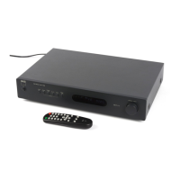
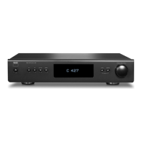
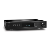
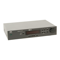
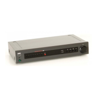
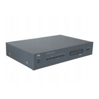
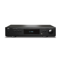
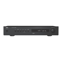
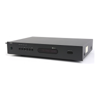
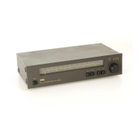
The NAD C 422 is a stereo AM/FM tuner designed to receive radio broadcasts. It features both AM and FM tuning sections, offering a range of functionalities for radio reception. The tuner includes an RDS (Radio Data System) decoder, which allows it to display additional information broadcast by FM stations, such as station name, program type, and other text messages. The device is equipped with a front panel for user interaction, including controls for power, blend, memory, FM mute/mode, AM/FM selection, preset/tune, and a display area. A rear panel provides connectivity options for FM and AM antennas, audio output, an IR input for remote control, and a 12V trigger input for integration with other NAD components.
Important Technical Specifications
Physical Specifications:
- Dimensions (Width x Height x Depth): 435 x 80 x 285 mm
- Net weight: 4 kg (8.8 lbs)
- Shipping weight: 5.1 kg (11.22 lbs)
AM Tuner Section:
- Input level expressed as the reading in open-circuit of 75-ohm source impedance signal generator.
- Usable Sensitivity (999/1000kHz): <30dBµ
- S/N Ratio (5mV in): ≥38dB
- THD (5mV in): <3%
- IF Rejection (450kHz): ≥36dB
- Image Rejection (F+2xIF): ≥28dB
- Selectivity: ≥17dB
- Output: 130 +/-20mV
- Loop Sensitivity (20dB S/N):
- 999/1000 kHz: <66 dB
- 603/600 kHz: <66 dB
- 1404/1400 kHz: <66 dB
- Frequency response (100 - 2.3 kHz, 5mV): +6 dB
**FM Tuner Section (for C and AH models):
- Input level expressed as the reading in open-circuit of 75-ohm source impedance signal generator.
- Usable Sensitivity (98 MHz): ≤13 dBµ
- Signal / Noise Ratio:
- Mono: ≥72 dB
- Stereo (60 dBµ, IHF wtd): ≥66 dB
- Frequency Response (20 Hz - 15 kHz, 60 dBµ): 0±1.0 dB
- Channel Separation (60 dBµ):
- 30 Hz: ≥33 dB
- 1 kHz: ≥42 dB
- 10 kHz: ≥32 dB
- Alternate Channel Sensitivity (40 dBµ, ±400 kHz): ≥60 dB (*C), ≥45 dB (*AH)
- Capture Ratio (40 dBµ): <3 dB
- AM Suppression (60 dBµ, 100% Mod.FM, 30% Mod AM): ≥65 dB
- Image Rejection (119.4 MHz): ≥85 dB
- I.F. Rejection (10.7 MHz): ≥78 dB
- Pilot Suppression (60 dBµ): ≥60 dB
- THD (60 dBµ, L=R 75 kHz for AH, 40 kHz Dev for C):
- Mono: ≤0.25%
- Stereo: ≤0.35%
- Auto-Search sensitivity:
- RDS Decode Sensitivity: <26 dBµ
Usage Features
The NAD C 422 offers several user-friendly features:
- Front Panel Controls: Dedicated buttons for "BLEND," "MEMORY," "FM MUTE / MODE," "AM / FM," and "PRESET / TUNE" allow for easy navigation and setting adjustments.
- Display Area: A clear display shows tuning information, station frequencies, and RDS data.
- Preset/Tune Control: A rotary knob facilitates tuning and preset selection.
- Software Version Display: Users can check the software version by pressing "PRESET/TUNE" and "TUNE UP."
- VFL Icon Illumination: All icons on the VFL (Vacuum Fluorescent Display) can be lit up by pressing "PRESET/TUNE" and "TUNE DOWN."
- CPU Resets: A CPU reset can be performed by pressing "PRESET/TUNE," "TUNE DOWN," and any other key.
- AM Step Change: The AM tuning step can be switched between 10KHz and 9KHz by adding or deleting D206.
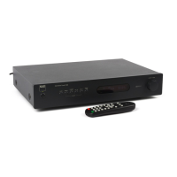
- Remote Control: The "IR IN" port on the rear panel indicates compatibility with a remote control, allowing for convenient operation from a distance.
- 12V Trigger Input: This feature enables the tuner to be turned on or off in conjunction with other NAD components that support 12V trigger signals, simplifying system control.
Maintenance Features
The service manual provides detailed procedures and diagrams for maintenance and repair:
- Disassembly Instructions: Clear steps are provided for removing the top cover, involving the removal of machine screws and tapping screws, and then tilting and lifting the cover.
- Block Diagram: A high-level overview of the tuner's internal architecture, showing the interconnections between major functional blocks like the front end, AM/FM IF, RDS decoder, CPU, VFD, and power supply. This helps in understanding signal flow and troubleshooting.
- Wiring Diagram: Detailed wiring connections are illustrated for the key board, power supply board, LED board, and main board, essential for tracing electrical paths.
- Adjustment Points Diagram: Specific points on the PCB are identified for alignment procedures, crucial for optimizing tuner performance.
- Instrument Setup: Diagrams illustrate the correct setup for FM, RDS, and AM measurements using signal generators, distortion meters, oscilloscopes, and millivoltmeters.
- Alignment Procedures: Step-by-step instructions are provided for FM/RDS and AM section alignments, including specific signal generator outputs, tuning frequencies, output indicators, adjustment points, and target values. This ensures the tuner operates within specifications.
- PCB Layout: Visual representations of the power supply board, key board, and main board layouts aid in component identification and placement.
- Schematic Diagram: Detailed circuit diagrams for the keyboard/display and tuner sections, showing individual components and their connections, are vital for in-depth troubleshooting and component replacement.
- IC Block Diagram: Internal block diagrams for key integrated circuits like the LC866448B (CPU), 24C08 (EEPROM), NJM78M56FA (voltage regulator), LM393D (dual voltage comparator), LA1837 (AM/FM IF), LC72723M (RDS decoder), and LC7218 (PLL frequency synthesizer) provide insight into their functionality.
- Electrical Parts List: A comprehensive list of all electrical components, including their reference numbers, part numbers, and descriptions, is provided. This list highlights critical parts (marked with a triangle) that are essential for fire and electric shock safety and must be replaced only with manufacturer-recommended parts. It also specifies part types for capacitors (CP-Polystyrene, CM-Mylar, CE-Electrolytic, CC-Ceramic, CTC-NPO) and resistors (RMF-Metal Film, RCF-Carbon Film).
- Exploded View and Parts List: Diagrams showing the disassembled components and a corresponding list with part numbers and descriptions facilitate mechanical repairs and ordering replacement parts.
- Packing Diagram: Information on how the product is packaged, including a list of packing materials, is useful for shipping and handling.
- Regional Specifications: Notes indicate specific part numbers or characteristics for USA/Canadian models (*AH) and European models (*C).
This manual serves as an indispensable resource for service technicians, ensuring proper diagnosis, repair, and maintenance of the NAD C 422 Stereo AM/FM Tuner.