Procedure:
Turn off the Nagra DAC with the front
power key, followed by the main switch
on the rear AC panel. Disconnect the
power cord.
Removing the top cover: Remove the 8
hex screws by using the supplied
ISO/Allen 2 mm key (2 on the left and
2 on the right side, 4 on the top).
Remove the 3 hex screws by using the
supplied ISO/Allen 2.5 mm key (1 on
the left and 1 on the right side, 1 on the
top). Remove carefully the top cover
from the housing.
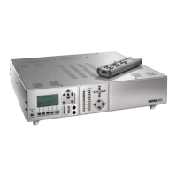
The DAC is basically fitted with 1 D/A
DSP converter pcb
Identify the above pcb inside the Nagra DAC.
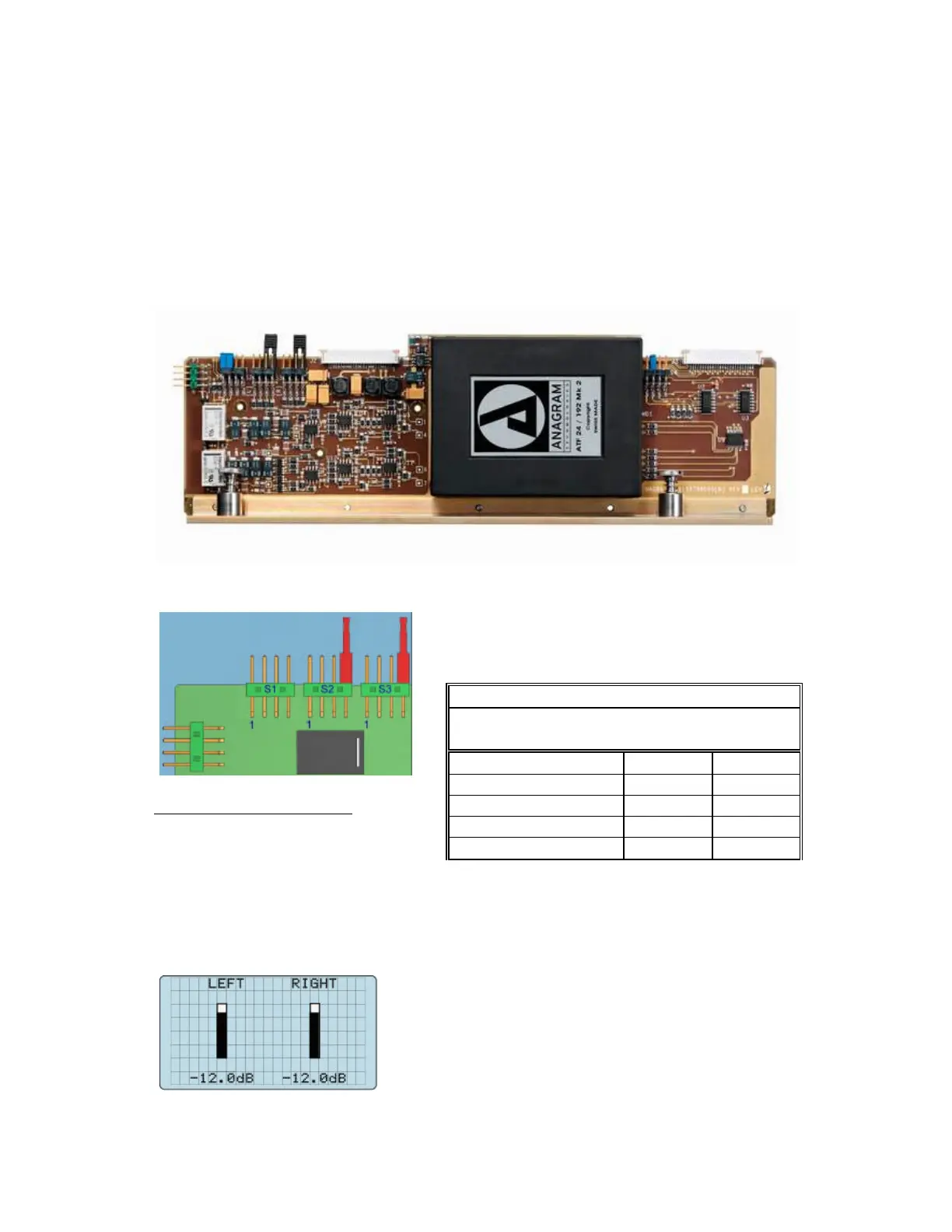
Select the adapted output level from the following
table:
Factory set to 0.775 Vrms
Example:
Setting the jumpers for S2 & S3 in position 2 gives an output voltage for 0 dB on the
modulometer of 2Vrms or +8 dBm.
VOLUME ADJUSTMENT
This display appears at the moment that
the up or down arrow key on the main
panel or second panel is pressed. It gives
an overall view concerning the MAIN
level (actually –12.0 dB).
Output level versus 0 dB on modulo meter
Jumper Output Output
position Vrms dBm
S2, S3 = 1 3.1 12
S2, S3 = 2 2 8
S2, S3 = 3 1.5 6
S2, S3 = 4 0.775 0
S2, S3 = none 6.2 18