4/09 IOM-BPTU
Installation and Operation Manual
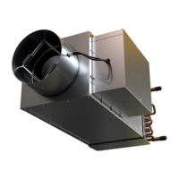
Bypass Terminal Units
Nailor Industries Inc. reserves the right to change any information concerning product or specification without notice or obligation.
Page 1 of 2
Receiving Inspection
After unpacking the assembly; check it for shipping damage. If any
shipping damage is found, report it immediately to the delivering
carrier. During unpacking and installation do not handle by the
control package.
Supporting the Assembly
Although the basic unit is light enough that it can be supported by
the ductwork itself, we recommend that it be independently
supported, especially when accessory modules, such as coils,
attenuators, or multiple outlets are present. When requested, unit is
supplied with field mounted hanger brackets for use with hanger
rod up to 3/8 (9.5) dia. Hanger brackets should be screwed into the
top of the unit casing. Hanger straps may alternately be used and
screwed directly into the sides or bottom of the unit casing. Use the
support method prescribed for the rectangular duct in the job
specifications.
Duct Connections
Slip each inlet duct over the inlet collar of the terminal. Fasten and
seal the connection as described in the job specification. The
diameter of the inlet duct for round inlets (unit size 4 through 10)
must be equal to the listed size of the terminal. The inlet collar of
the terminal is made 1/8 (3) smaller than listed size in order to fit
inside the duct. Unit size 12 through 16 utilize flat oval inlet collars.
The flat oval inlets are undersized for flexible duct connection. For
hard inlet duct connections, refer to submittal drawing for
dimensional data.
Important: Do not insert ductwork inside the inlet collar of the
assembly. For optimum performance, 2 to 3 equivalent diameters
of straight duct should be installed prior to the inlet of the unit. All
ducts should be installed in accordance with SMACNA guidelines.
The outlet end of the terminal is designed for use with slip and drive
duct connections. A rectangular duct the size of the terminal outlet
should be attached.
Field Wiring
All field wiring must comply with NEC and local codes. Electrical,
control, and piping diagrams can be found on labels affixed to the
exterior/interior of the control enclosure box. All Nailor electric
heaters are staged per specifications. The installing electrician
should rotate the incoming electric service by phase to help
balance the building electric load.
Fuse size designates the size of the internal fuse if it is supplied.
Maximum Overcurrent Protection (MOP) designates the largest
breaker or fuse in the electrical service panel that can be used to
protect the unit.
Control Start-up, Operation
Your local Nailor Representative can provide detailed information
about start-up and operating procedures for Nailor’s digital, analog,
and pneumatic controls. For specific information on controls
provided by other manufacturers, contact the specific
manufacturer’s local or national office. This applies whether the
controls were factory or field mounted.
Note: Digital controllers may use specific communication
addresses based on Building Management Systems Architecture
and original engineering drawings. Installing the terminal in a
location other than that noted on the label may result in excessive
start-up labor.
Balancing Procedure
This balancing procedure assumes that the fan supplying the
system maintains a constant static pressure in the supply duct to
the terminal unit. Bypass terminal units are pressure dependent and
will need rebalancing if system duct static pressure changes.
The 3400 series are shipped with both inlet and bypass balancing
dampers as standard to permit ease of field balancing and to ensure
accurate adjustment and optimum operation.
1. Fully open the dampers of all supply outlets on the discharge
duct from the terminal unit.
2. Place terminal in the full open position, supplying 100% air to the
occupied space by adjusting the thermostat to full cooling.
3. Adjust the balancing dampers located in the terminal inlet to
provide the required total airflow.
4. Starting with the outlet furthest downstream, adjust the damper
of each air outlet to the required air volume.
5. Take a static pressure reading at the terminal unit, using a
magnehelic gauge or equivalent.
6. Adjust the room thermostat to full heating to provide 100%
bypass airflow or the minimum air volume to the room, if a
mechanical minimum air volume stop is utilized. An indicator mark
on the end of the driveshaft shows damper position, 90° rotation
CW to close.
7. Adjust the bypass outlet damper(s) on the terminal until the static
pressure reading equals that obtained in step 5.
8. Re-adjust the room thermostat to the desired setpoint
temperature. The terminal is now balanced.
Dimensions are in inches (mm).
 Loading...