Nailor Industries, Inc. reserves the right to change any information concerning product or specification without notice or obligation.
(UNITE TERMINALE @
VENTILATEUR INTEGRÉ)
(DIAMETRE D'ENTRÉE)
:
(VOLTAGE DE CONTRÔLE)
:
(SEQUENCE DE CONTRÔLE)
:
:
AMPS AMPACITY
(AMPÈRES) (AMPACITÉE)
TOTAL EACH STG. TOTAL EACH CIR. EACH STG. TOTAL EACH CIR. EACH STG. EACH CIR.
(TOTALE) (CHAQUE (TOTALE) (CHAQUE (CHAQUE (TOTALE) (CHAQUE (CHAQUE (CHAQUE
ÉTAPE) CIRCUIT) ÉTAPE) CIRCUIT) ÉTAPE) CIRCUIT)
HEATER (CHAUFFAGE)
3.0 3.0 3.6 3.6 3.6 4.5 4.5 4.5
MOTOR (MOTEUR)
TOTAL (TOTALE)
EACH ELEMENT RATED @
1.0 KW @ 277 VAC. 14
(CHAQUE ELEMENT CLASSIFIER A)
USE WIRE SUITABLE FOR AT LEAST 75
o
C
UTILISER UN FIL METALIQUE QUI CONVIENT AU MOIN 75
o
C
L1 IS COLOR CODED BLACK , L2 IS BLUE, L3 IS RED L1 EST COLORÉ NOIRE, L2 EST BLUE , L3 EST ROUGE,
CONTROL WIRES CODED AS MARKED LES FILS DE CONTRÔLE SON INDENTIFIÉE COMME MARQUE,
USE COPPER CONDUCTORS ONLY. UTILISÉ DES CONDUCTEURS DE CUIVRE SEULEMENT.
USE CLASS K, RK1, A2D OR A6D FUSE OR HACR BREAKERS. UTILISÉ DES FUSIBLES CLASS K, RK1, A2D, OU A6D OU HACR DISJONCTEURS,
MAX FAN CLG / MIN DEADBAND (CFM) : MAX FAN CLG / MIN DEADBAND (L/S) :
INTERNAL FUSE SIZE
(IF SUPPLIED)
MIN. HEATING CFM (MIN. PCM) :
AWG. MIN WIRE SIZE (MIN DIAMETRE DE FIL ) :
15 15
(NOMBRE DE RANGÉES SERPENTIN
EAUCAUDE)
SERIAL NO. (NO. DE SÉRIE)
KW/WATTS
MAX FAN CLG / MIN Bande Morte (L/S) :
(NOMBRE DE RANGÉES SERPENTIN EAU RÉFRIGERÉÉ)
MAX FAN CLG / MIN Bande Morte (CFM)
MAX. OVERCURRENT PROTECTION
(RESISTANCE DES FUSIBLE MAX.)
(VOLTAGE DU MOTEUR)
(AMPERAGE DU MOTEUR)
EACH CIR.
(CHAQUE
CIRCUIT)
9/18 IOM-DOAS
Page 5 of 8
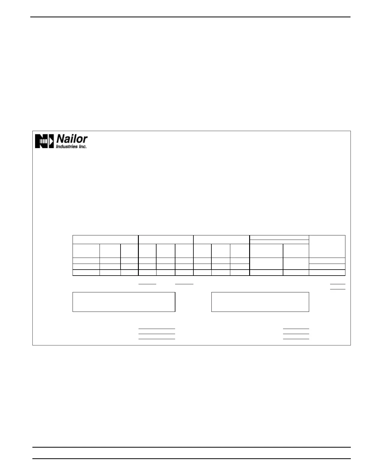
Label Example
mounting lugs holding the fan assembly to the discharge panel,
and remove the assembly through any convenient access panel.
Do not allow assembly to hang from wiring. If removing motor from
blower, first loosen the set screw holding the blower wheel to the
motor shaft. Remove the three screws holding the motor to the fan
housing, and slide motor and fan housing apart.
To put the assembly back together, reverse the procedure. Be sure
to align the blower set screw with the flat section of motor shaft.
Note: Over-tightening motor mounting screws may crush isolation
bushing, causing excessive fan noise.
Primary Air Damper Replacement
Nailor’s primary air valve assembly is not repairable. The entire
assembly should be replaced if it is damaged.
Labels
Each 33SZ unit is shipped with a nameplate label affixed to the
control casing. Principle nameplate data on the label typically include
Order-Serial number, Model number, Unit size, Motor horsepower,
Amperage, MOP, Heater (if present) data, Supply voltage and
Airflows. Also provided are calibration, airflow, as well as other labels
as necessary. We suggest that you read all labels before beginning
installation. If you have any questions, please contact your local
Nailor Representative. Their phone numbers can be found on our
website at www.nailor.com.