3/11 IOM-AECVAV
Nailor Industries Inc. reserves the right to change any information concerning product or specification without notice or obligation.
Page 6 of 10
CALIBRATION PROCEDURE FOR AIR VOLUME ADJUSTMENTS MADE AT THERMOSTAT
Thermostats are factory calibrated when minimum and maximum airflow limits are provided. Field calibrations are as follows:
Minimum and maximum setpoints (air volume limits), are set at the thermostat. Check the CSP-5002 controller to ensure that the minimum
and maximum potentiometers are dialed completely out (min. CCW, max. CW), so that the thermostat signal is not restricted.
A – Required Tools:
1. Small flat blade screwdriver 1/8" / 3 mm 3. Hex Wrench 1/16" / 2mm for the cover screws
2. Digital voltmeter w/DC range to hundredths 4. A test lead (HSO-5001) is recommended for meter readings
B – Remove Thermostat Cover:
Thermostat cover is removed by turning the two set screws CW, (which are located on the short sides of the thermostat). Remove cover and
setpoint slider stops if installed.
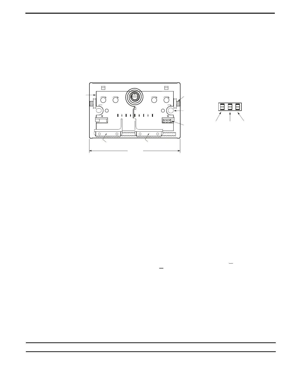
Figure 9. Thermostat scaleplate detail.
CTE – 5101 SINGLE SETPOINT THERMOSTAT
(DA T1 with limits, T3 without limits)
1. Ambient temperature at the thermostat must be between 55
O
F – 85
O
F (13
O
C – 29
O
C).
2. Adjust the setpoint slider all the way to the right for minimum cooling. Connect voltmeter to the cooling (right side) voltmeter taps. The
center and right tap provide the VDC readings (min/max airflow). The center and left tap provide the actual air volume (live velocity)
reading when thermostat V1, is connected to the controller OUT terminal.
3. Read the VDC across the taps. Adjust the MIN INCR potentiometer to the VDC equal to the desired air volume as shown on the chart.
NOTE: The minimum setpoint must be set first. Adjustment of the minimum potentiometer directly affects the maximum setpoint.
4. Adjust the setpoint slider all the way to the left for maximum cooling.
5. Read the VDC across the taps. Adjust the MAX INCR potentiometer to the VDC equal to the desired air volume as shown on the chart.
NOTE: The maximum setpoint must be set last. Adjustment of the minimum potentiometer directly affects the maximum setpoint.
6. Return the setpoint slider to the desired setpoint. Install the optional setpoint stops if required and replace thermostat cover.
CTE - 5103 DUAL SETPOINT THERMOSTAT (Heat / Cool Changeover)
(DA T1/T3. RA T2/T4. T1, T2 with limits, T3, T4 without limits)
Cooling side of thermostat
1. Follow steps 1 through 5 for the CTE-5101 thermostat. Note: Be sure to adjust the cooling setpoint slider all
the way to the left for
maximum cooling. (The heating setpoint sider will have to be adjustable all the way to the left also).
Heating side of thermostat
1. Ambient temperature at the thermostat must be between 55
O
F - 85
O
F (13
O
C - 29
O
C).
2. Adjust the heating setpoint slider all the way to the left for minimum heating. Connect voltmeter to the heating (left side) voltmeter taps.
The center and right tap provides the VDC readings (min/max airflow).
3. Read the VDC across the taps. Adjust the MIN INCR potentiometer to the VDC equal to the desired air volume as shown on the chart.
NOTE: The minimum setpoint must be set first. Adjustment of the minimum potentiometer directly affects the maximum setpoint.
4. Adjust the heating slider all the way to the right for maximum heating.
5. Read the VDC across the taps. Adjust the MAX INCR potentiometer to the VDC equal to the desired air volume as shown on the
provided chart.
NOTE: The minimum setpoint must be set first. Adjustment of the minimum potentiometer directly affects the maximum setpoint.
6. Return both setpoint sliders to the desired setpoints. Install the optional setpoint stops if required and replace thermostat cover.
V
ELOCITY
MIN. & MAX.
VELOCITY
M
ETER
T
APS
C
OVER MTG.
S
CREWS (2)
RETAINING
PINS (2)
SCALE PLATE
(°F OR °C)
70
KMC Controls
50 90
METER TAP
HEATING COOLING
VV
MAX/AUX
INCR
MIN
INCR
MIN
INCR
MAX
INCR
METERS
TAPS
METERS
TAPS
3
1/4" (83)
HEATING SLIDER
(WHERE APPLICABLE)
COOLING
SLIDER