11/11 IOM-RFTU
Installation and Operation Manual
Retrofit Terminal Units
Nailor Industries Inc. reserves the right to change any information concerning product or specification without notice or obligation.
Page 1 of 2
Receiving Inspection
After unpacking the assembly check it for shipping damage. If
any shipping damage is found, report it immediately to the
delivering carrier. During unpacking and installation do not
handle by the inlet velocity sensor or the optional control
package.
Installation
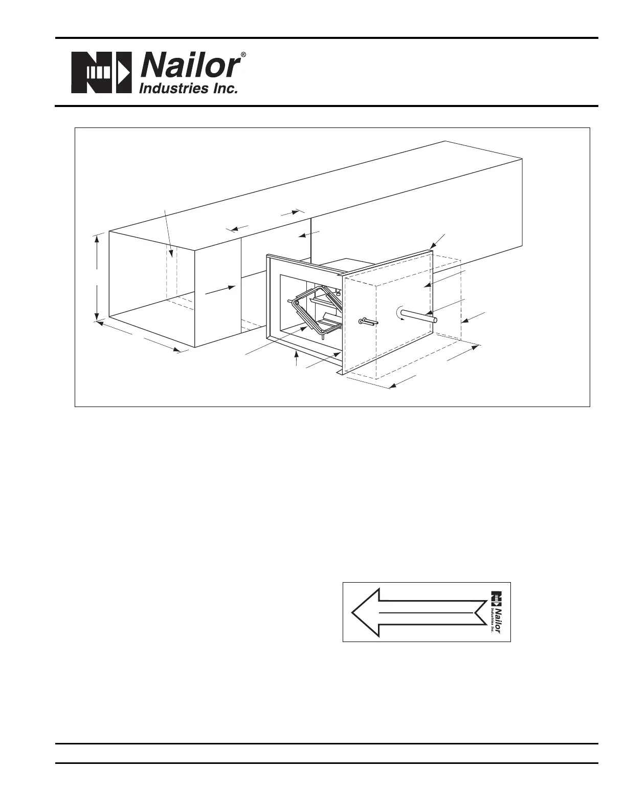
For installation, cut a rectangular opening in the side of the duct.
The opening should be the height of the duct and 12" (305) wide
as shown in Figure 1. If the duct has internal insulation, cut a 1
inch wide strip of insulation inside the duct. The strip of
insulation removed will allow the assembly to slide in smoothly.
Make sure the inlet airflow sensor is installed upstream of the
damper and in direction of airflow. Use sheet metal screws
along the left and right side of the mounting plate as well as the
top and bottom flanges in order to secure the mounting plate to
the rectangular duct. Seal as necessary in order to meet
applicable standards. Any control components can now be
installed and connected.
Field Wiring
All field wiring must comply with NEC and local codes.
Electrical, control, and piping diagrams can be found on labels
affixed to the exterior / interior of the control enclosure. Fuse
size designates the size of the internal fuse if supplied.
Maximum Overcurrent Protection (MOP) designates the largest
breaker or fuse in the electrical service panel that can be used.
Control Start-up, Operation
Your local Nailor Representative can provide information about
start-up and operating procedures for Nailor’s digital, analog,
and pneumatic controls. For specific information on controls
provided by other manufacturers, contact the specific
manufacturer’s local or national office.
Labels
Retrofit terminals units are shipped from the factory with the
following information label.
C
CW
TO
O
PEN
M
OUNTING PLATE
DRIVE SHAFT
FULL ELECTRICAL CONTROLS
ENCLOSURE FOR FACTORY MOUNTED
D
DC AND ELECTRONIC CONTROLS
14" x 10" x 6" DEEP (356 x 254 x 152)
DUCT OPENING
BY OTHERS
1
2
"
(
3
0
5
)
A
I
R
F
L
O
W
O
VERLAP FLANGE
(TOP & BOTTOM)
1
6
"
(
4
0
8
)
FULL
GASKET
MULTI-POINT
AVERAGING
FLOW SENSOR
H*
W*
IF LINED DUCT, REMOVE
I
NSULATION TO ALLOW ASSEMBLY
T
O INSTALL SMOOTHLY
Airflow Direction Label
AIR FLOW (ECOULEMENT DE L'AIR)
AIR FLOW (ECOULEMENT DE L'AIR)
LOW (BAS) HIGH (HAUT)
HIGH (HAUT) LOW
* Refer to submittal for duct size dimensions.
Figure 1: Model 36VRS - Slide-In Retrofit Terminal Unit
Dimensions are in inches (mm).