5.4 Installing dimmer
5.4.1 Divide the dimmer into two parts.
(Operation Component,Panel and Drive Component)
5.4.2 Carefully position all wires inside the wall-box, leaving enough space to insert the dimmer housing.
5.4.3 Put the Drive Component inside the wall-box and align at the screw holes(①②)
5.4.4 Tighten the screws(①②) to let the Drive Component stick to the Junction Box.
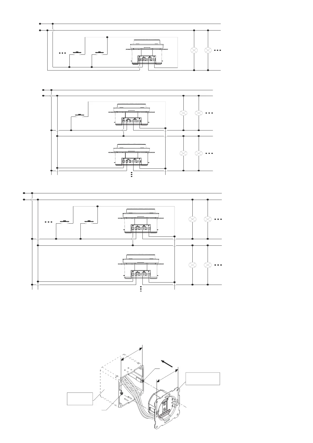
Multipl self-reset switches control one dimmer wiring diagram
L
N
Push switch
(Se lf-reset
switch)
Push switch
(Se lf-reset
switch)
One self-reset switch control multiple dimmers wiring diagram
L
N
Push switch
(S e lf-res et
switch)
Multiple self-reset switches control multi-way dimmers wiring diagram
L
N
Push switch
(S e lf-res e t
switch)
Push switch
(S e lf-res e t
switch)
②
6
0
mm
6
0
mm
①
电源和执行组件
Drive Component
Junction Box