Do you have a question about the NAPCO GEM-RP1Ca and is the answer not in the manual?
Steps to test the audible alarm functionality of the system.
Steps to test the system's communication with the central station.
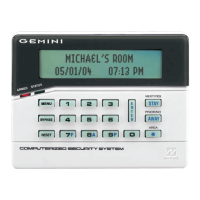
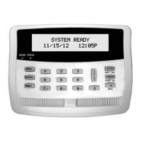
Displays system status messages, zone descriptions, etc.
Indicates system readiness for arming (green).
Indicates system is armed (red) or an alarm occurred (flashing).
Selects system functions displayed in the window.
Deactivates or unbypasses selected zones from the system.
Resets system troubles, displays, or smoke detectors.
Used for entering codes, zone numbers, etc.
Entry key to execute codes or selected functions.
Bypasses interior zones or scrolls display forward.
Cancels entry delay or scrolls display backward.
Selects and arms/disarms other areas.
Used with [*] for Fire, Auxiliary, or Police emergencies.
Verifies system readiness, identifies and bypasses faulted zones.
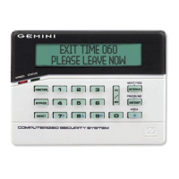
Steps to arm the system, including entering code and exit delay.
How to arm with a faulted Priority Zone and potential issues.
Addresses system troubles like low battery and options to arm.
How to arm specific areas or all areas in a partitioned system.
Allows free movement within premises while perimeter zones are armed.
Cancels entry delay for immediate alarm on entry door violation.
Activates signals for Fire, Auxiliary, or Police emergencies.
Steps to disarm the system upon entry.
How to identify and silence an active alarm.
Uses a special code to send a silent alarm during forced disarming.
How Day Zones function and indicate troubles when disarmed.
How 24-Hour Zones function, armed at all times.
Steps to take during a fire alarm and how to silence it.
How to handle a problem in the fire-circuit and silencing the sounder.
Guidance on creating and practicing a fire escape plan.
Important safety procedures to follow during a fire.
Explains why fire alarm systems may fail to provide protection.
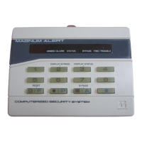
Identifies zones that are not secured.
Shows zones that have been manually bypassed.
Lists zone numbers and their descriptions.
Tests the alarm for about 2 seconds.
Allows dialing of programmed telephone numbers.
Shows 2-digit error codes for detected system problems.
Shows alarms that have occurred on Fire Zones.
Shows trouble conditions detected on Fire Zones.
Shows programmed opening and closing schedules.
Displays total system status at a glance in a partitioned system.
Sounds a tone when a programmed zone is opened while disarmed.
Simultaneously turns on designated Day Zones.
Feature intended for commercial applications only.
Clears system trouble indications, some require manual reset.
Clears specific sensor trouble error messages.
Manually starts exit delay, useful for communication issues.
Sends a communicator test to the central station.
Shows all alarm conditions that have occurred.
Shows all events that have occurred in the system.
Shows fire alarms, troubles, and restores.
Logs system openings (disarmings) and closings (armings).
Logs system troubles and other system events.
Allows arming to be delayed by 1-4 hours.
Shows the programmed autoarm schedule.
Activates programming mode from Keypad No. 1.
Activates manual download mode for installer/servicer.
Checks status and condition of wireless transmitters.
Turns programmed relay groups on or off.
Details about the system's communication capabilities.
Delay allowing system reset before reporting to central station.
Notifies central station on system arming/disarming.
Bypassing or unbypassing zones with a valid code.
Bypassing zones via Display Zone Faults or Directory screens.
Starts exit delay after central-station ringback (commercial systems).
How exit delay behaves after re-entry or expiry.
Used to customize user codes and zone descriptions.
Steps to access the User Program Mode from Function Mode.
Steps to program or change user codes for arming/disarming.
Steps to enter identifying descriptions for each zone.
Displays like 'SYSTEM READY', 'PLEASE WAIT', 'EXIT TIME', 'ENTRY TIME', 'SYSTEM ARMED'.
Displays indicating zones faulted or system troubles.
Messages indicating an alarm or fire condition.
Messages for invalid codes, entry attempts, or arming failures.
Indicates general system problems like power, battery, or communication failures.
Messages like Overview Mode and remote-access keypad status.
Delay allowing system reset before reporting to central station.
Code used to remotely unlock a door.
Code for silent alarm during forced disarming.
Turning the system on or off using a code and button.
Provides power during electrical failure.
Enables manual removal of zones from the system.
Monitors reports and notifies authorities.
Keypad beep when a zone is opened while disarmed.
Time interval for permitted closing (arming).
Reports system events to the central station.
The system's brain controlling all functions.
Listing of programmed zone descriptions.
Quick arming by pressing the [ON/OFF] button.
Delays allowing exit/entry without immediate alarm.
Arming without entry delay for immediate alarm.
Bypasses interior zones or selects zone groups.
Puts control-panel functions at fingertips.
Low-security mode for area arming in partitioned systems.
Time interval for permitted opening (disarming).
High-security mode for area arming display.
Activates emergency signals with [*] button.
System subdivided into multiple independent subsystems.
Keypad alert of an impending alarm.
Transmission notifying of system status changes.
Indicates a weak transmitter battery (wireless systems).
Periodic test report from wireless transmitters.
Beep verifying central station receipt of closing report.
A code intended for temporary use.
Local warning device at keypad for various alerts.
Problem detected in the system (e.g., low battery, power failure).
Zone fault or problem preventing arming.
Personalized code for arming/disarming the system.
Turns all Day Zones on or off simultaneously.
A time interval, e.g., Opening/Closing Window.
Defines Auto-Bypass, Burglary, and Day Zones.
Provides exit/entry delay for interior devices.
Detects fire alarms or trouble conditions.
Circuits within premises, can be bypassed using INTERIOR Button.
Zone that prevents arming if in trouble.
A Priority Zone that can be bypassed using the [RESET] key.
Zone that can be individually bypassed using the [BYPASS] Button.
Zone armed and ready at all times for emergencies.
Indicates a loss of AC power.
Indicates the system battery is low.
Indicates failure to communicate with the central station.
Supervisory failure for a specific RF transmitter.
Low battery condition for a specific RF transmitter.
Failure of the receiver to respond.
Indicates a failure during a system download.
Indicates a problem with the telephone line.
Indicates the system has performed a cold start.
Failure of a specific keypad to respond.
Tamper condition detected on a specific keypad.
Failure of an expansion zone module to respond.
Tamper condition on an expansion zone module.
Failure of the relay board to respond.
Tamper condition for a specific RF transmitter.
Indicates the receiver is jammed.
Tamper condition detected on the receiver.
Low battery for a specific key fob transmitter.
Error in the user program memory.
Error in the dealer program memory.
Indicates the system has shut down.
Failure related to sensor activity.
Indicates a failure on the burglary bus.
General service message code.
Indicates an error with receiver capacity.