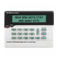
NAPCO Gemini C-Series Control Panel Installation Instructions--Volume 2
Installation Instructions, Volume 2 Page 59
TELEMETRY COMM
The event Log will read: TROUBLE: TELEMETRY FAIL
Trouble Restore: TELEMETRY FAIL
Keypad programming Address Location 1100 = [●][ ] 4 - Telemetry Trouble
Telemetry Failure 8 - Telemetry Fail
Telephone Numbers See Fire Glossary
Test Timer
The test timer schedule is programmed using NAPCO's PCD-Windows Quickloader Software. If Test Timer is programmed,
an automatic test report will be transmitted to the central station on the scheduled day(s) at the scheduled time. (UL installa-
tions require a report at least every 24 hours). To report test timer, select Report Test Timer and program a report code. Pro-
gram the Test Timer event schedule and reporting time.
Timeout
Specifies the length of time that an alarm, alert, or delay will remain active. Burg PGM1 Access Control Timeout, Abort-Delay
Time, and Chime Time must be programmed, or the feature will not activate. See Time Selection.
Time Selection
Any timeout up to those shown in the "TIME SELECTION" table may be programmed. Note that each of the time durations
are programmed in two locations; the first location has an assigned time factor of 16, the second a time factor of 1. The fol-
lowing times are programmable as referenced in the TIME SELECTION table.
Note: If both programming locations are left blank, refer to the notes in the Time Selection table for feature timeout.
To select a time up to 15 seconds, 15 minutes, 15 hours, or 15 days, program the respective entry into the second box only;
do not program the first box. To select a time greater than 15 seconds, 15 minutes, 15 hours or 15 days, program both boxes
as follows:
1. For the feature selected, choose an appropriate time in units shown (all seconds, minutes, hours, or days — not min-
utes and seconds, etc.).
2. Divide the time chosen by 16. Enter the quotient in the 1st BOX and the remainder in the 2nd BOX.
3. Check entries by adding the contents of the 2nd BOX to 16 times the contents of the 1st BOX. (Remember that a
"zero" entry represents 10).
Example:
Program Entry Delay 1 for 1 minutes.
1. Entry Delay 1 is in units of seconds, thus delay time is 90 seconds.
2. Divide by 16: 90/16 = 5 (quotient) + 10 (remainder).
3. Enter the quotient in the 1st BOX and the remainder in the 2nd BOX
4. Check entries (remember, a "0" entry = 10): (16x5) + 10 = 90
TouchTone Dialing Only
Rotary Dialing Only
TouchTone Dialing with Rotary Backup
Select TouchTone Dialing Only if the subscriber has TouchTone service. TouchTone dialing is faster than rotary dialing, but
not always as reliable.
For the communicator to use TouchTone on all dial attempts, program TouchTone Dialing Only. To use TouchTone on the
first attempt with subsequent Rotary dial, program TouchTone Dialing with Rotary Backup. TouchTone Dialing Only will over-
ride TouchTone Dialing with Rotary Backup if both are selected. Note that if Backup Reporting is also selected, the communi-
cator will alternate between TouchTone and rotary dial to reach Telephone 1, then Telephone 2. See Backup Report on
Telco 2.
Trouble
An abnormal zone condition (a break in a normally-closed loop; a short on a normally-open loop; or either on an end-of-line-
resistor supervised loop) when disarmed.
Trouble on a Burglary Zone is automatically displayed at the keypad unless Disable Zone Fault Scrolling (Auto Status) is pro-
grammed. If a Burglary Zone is in trouble, it will go into alarm about 10 seconds after arming. However, if Auto Bypass is
programmed, the keypad will beep upon arming (does not apply to selective- or group-bypassed zones).
Trouble (open and/or short circuit) on a Day Zone/Trouble is indicated by a pulsing sounder; display the Day Zone(s) in trou-
ble on the LCD. Keypad indications are reset by the C button unless Reset Day Zone/Trouble With Arm/Disarm is
selected.
Trouble on a Fire Zone will be indicated by the "FIRE/TRBL" reminder and the sounder. An open circuit (trouble) will cause a
flashing "FIRE" display and a pulsing sounder after a 15-second delay. (A short circuit will cause an alarm condition: steady-
on "FIRE" display and pulsing sounder). The C button will silence the sounder. Clear the trouble, then press the C
button once again. The keypad will reset after a brief delay.
BURGLARY GLOSSARY
 Loading...


