6 StarLink
™
SLE-LTE Commercial Series Alarm Communicators -- Installation Instructions
panel terminals TIP and RING (DACT interconnect
wiring to the radio). Do NOT connect the StarLink
radio terminals TB10-13 to house telephone lines
(RJ31X modular plug wires, etc.).
Wiring Methods
Strip wire carefully to avoid exposed conductors after
installation, etc.
Use UL Listed wire, ensuring that all conductors are to be
insulated for the maximum voltage of any conductor in
the enclosure
All wiring methods must be performed in accordance with
NFPA 70, Articles 725, and 800
STEP 4: APPLY POWER
Attach primary (top left) antenna before applying
power !
The StarLink radio requires +12 or 12/24VDC. It draws
less than 71mA during standby, and almost 200mA dur-
ing transmissions (for less than 1 second).
STEP 5: SIGNAL VERIFICATION
Verify Online: To verify that the signals have been
received by the StarLink radio LTE Network online, go to
www.napconoc.com, log in with your Username and
Password, enter your Company ID number and the Star-
Link LTE Radio Number, then click Signal Log.
IMPORTANT: Verify that the signals transmitted by the
StarLink radio have been properly received by your central
station before leaving the premises.
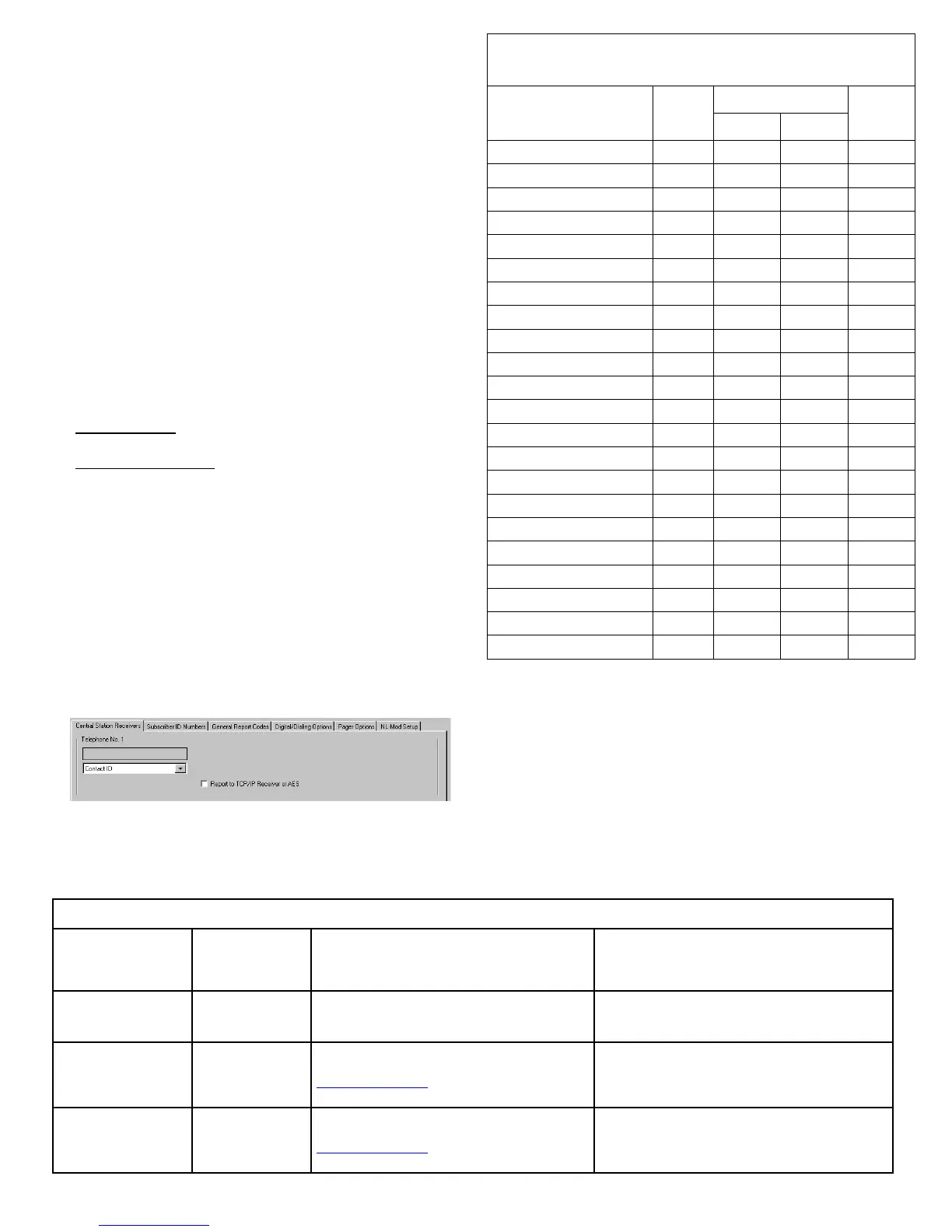
NAPCO CONTROL PANEL PROGRAMMING
To program the central station receiver reporting format,
use PCD-Windows Quickloader download software. Open
the Digital Communications screen, Central Station Receiv-
ers tab, as shown in the following image. A "Point
ID" (also called "Contact ID") receiver format programming
example is shown:
The radio can transmit to any central station capable of re-
ceiving SIA Contact ID via DACR technology or the DSC
Sur-Gard System II or Sur-Gard System V central station
receivers via TCP/IP.
STARLINK RADIO RELATED EVENT
REPORT CODES
(Contact ID by default)
EVENT AREA
CONTACT ID
CODE ZONE #
IN 1 Fire
0 E110 990 1A
IN 2 Panic
0 E120 992 22
IN 3 Trouble
0 E300 993 F3
Low Battery/Voltage
0 E302 994 F4
Tamper Trouble
0 E341 995 F5
Line Cut
0 E352 996 F6
Reboot
0 E625 997 F7
IN 1 CO (Carbon Monoxide)
0 E162 998 18
Panic Alarm*
E123
Holdup Alarm*
E122
Medical Alarm*
E100
24 hour Aux. Alarm*
E150
24 hour Aux. Restore*
R150
Burg Perimeter Alarm*
E131
Burg Interior Alarm*
E132
Keypad Holdup Alarm (ambush)*
E121
Keypad Panic Alarm*
E123
Keypad Emergency Alarm*
E140
Opening*
E401
Closing*
R401
A.C. Trouble*
E301
Tel 1 Fail*
E351
*Not generated by the StarLink radio.
PULSE
4/2
SIGNALS ORIGINATED AT THE NOC
NOC Originated
Alarms
Contact ID
Event Data
Sent
Initiated By Comments
Supervisory Fail E356 A00 Zn000
Automatically by NOC if fail to receive any signal
from StarLink radio within Supervisory Timeout
duration.
For Auto Enroll, uses captured telephone number,
Sub ID and format. For Dealer Programmed, uses
entered telephone number, Sub ID and format.
Press to Send
Test Signal
E601 A00 Zn000
Manually by dealer from the Management Center
Signal Log screen (located at
www.napconoc.com). Sends test into CS receiv-
er.
Same comment as above.
Press to Send
Radio Test
Not Applicable
Nothing sent to
CS receiver
Manually by dealer from the Management Center
Checkins screen (located at
www.napconoc.com). Sends a command to the
StarLink radio to force a check-in to the NOC.
----
Note: A receiver reporting format must be entered for
each telephone number used, but each telephone number
may be assigned a different format.
CAUTION: The installer should always be certain an
area code is programmed into the control panel.
Optional: If you wish the StarLink radio to report a code
and zone number (Contact ID by default) to the central sta-
tion in response to a triggered input event, see the table on