StarLink
™
SLE Commercial LTEVI & LTEAI Series Dual-Path Alarm Communicators -- Installation Instructions 11
(STARLINK RADIO HOUSING)
StarLink Radio Terminals
PC Board: All connections are power limited except AC Mains and battery terminals.
LOCAL
DOWNLOAD
TELCO
SECONDARY
TELCO
PRIMARY
ETHERNET
1
(+)
2
(‒)
POWER PGM3 IN1 IN2 IN3
3
(‒)
4
(+)
5
(+)
6
(‒)
8
(‒)
7
(+)
9
(+)
10
(‒)
12
(‒)
11
(+)
13
EGND
19
N/O
21
N/C
20
C
IN4 IN5
OUT1
22
N/C
24
N/O
23
C
OUT2
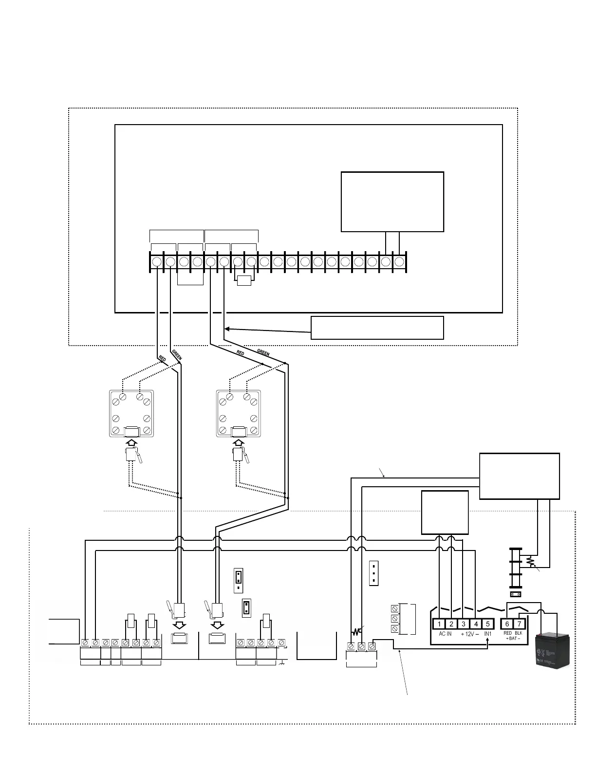
Wiring Diagram for Generic FACPs
without TELCO RJ Sockets
FACP PC BOARD
(CONTROL PANEL HOUSING)
SECONDARY TELCO
PRIMARY TELCO
IN PHONES IN PHONES
10kΩ
Power Supply (SLE-ULPS-R)
Optional; if not used, connect 10K
resistor between terminals 9 and
10 (IN4)
StarLink
BATTERY
(+)
RED
(–)
BLACK
8 9 10
N/C
COM
N/O
J2
Note: Battery
leads are not
power limited
10kΩ
10kΩ
10kΩ
Refer to section "SUPPLYING POWER".
DO NOT
USE EOLR
EOLR
(J2 jumper off)
(This connection only used with
Power Supply SLE-ULPS-R)
(These connections only
used without Power Supply)
To FACP Zone
Dedicated to Radio
Trouble*
EOLR
JP1
--Shunt JP1 on
bottom 2 pins
when using the
SLE-ULPS-R
--Shunt on top 2
pins when not
using the SLE-
ULPS-R
RJ31X
RING
TIP
GREEN
RED
GREEN
RED
WIRE DIRECTLY TO CONTROL
PANEL (USE FOR SHORTER DISTANCES)
OPTIONAL
: WIRE TO RJ31X
(USE FOR LONGER DIST
ANCES)
RJ31X
RING
TIP
GREEN
RED
WIRE DIRECTLY TO CONTROL
PANEL (USE FOR SHORTER DISTANCES)
OPTIONAL
: WIRE TO RJ31X
(USE FOR LONGER DIST
ANCES)
GREEN
The feature "Tip/Ring Wiring Fault
Report" is required for supervision.
RED
JP2
Remove shunt
on JP2 to enable
TELCO 2 trouble
*Not required if JP2 shunt is removed and FACP monitors TELCO 2.
When using JP2 option (monitoring Telco 2) with power supply wire:
1. Move Power Supply IN1 from Radio OUT1 terminal 21 to power
supply terminal 4 (-).
2. Do not wire power supply trouble relay to FACP zone.
3. Wire power supply terminals 9 and 10 in series with the 10K
EOLR to Radio IN4 (+).
4. Program IN4 to report power supply trouble.
Optional: When Power Supply
SLE-ULPS-R is not used, connect
FACP AUX/Remote Fire Power or
Listed power supply (+12V or
+24V) to StarLink terminals 1 and
2 (observing polarity)
(+) (‒)
+12V or +24V
AUX/Remote Fire
PWR
Either the TRF12/
T123 (16.5V / 20VA)
transformer or the
chassis-mounted
16.5VAC / 20VA
transformer
J7
J7: Remove shunt
to disable 10K
EOLR across pins 1
and 8 of primary
TELCO input. Do
not remove if "Tip/
Ring Wiring Fault
Report" is
enabled.
 Loading...


