10 StarLink
™
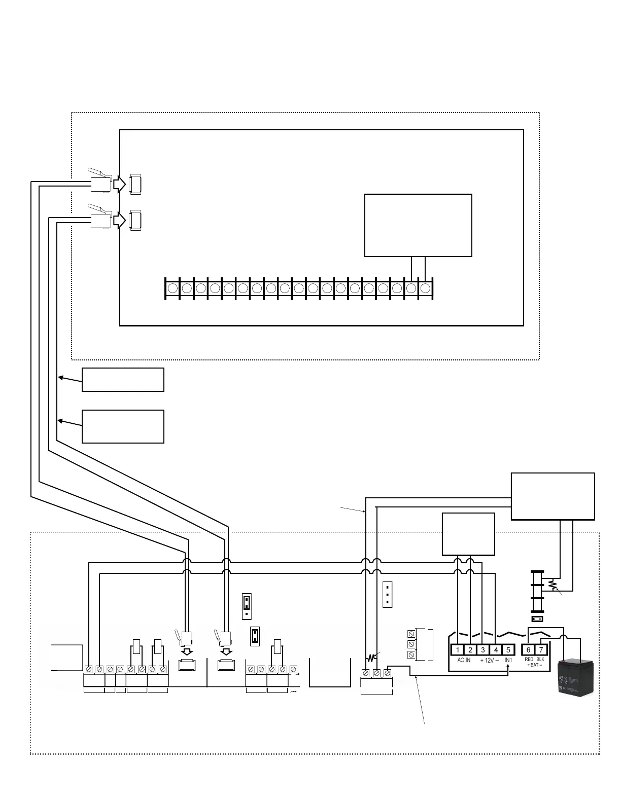
SLE Commercial LTEVI & LTEAI Series Dual-Path Alarm Communicators -- Installation Instructions
Wiring Diagram for Generic FACPs
with TELCO RJ Sockets
FACP PC BOARD
(CONTROL PANEL HOUSING)
Refer to section "SUPPLYING POWER".
TELCO RJ SOCKET (SECONDARY)
(STARLINK RADIO HOUSING)
StarLink Radio Terminals
PC Board: All connections are power limited except AC Mains and battery terminals.
LOCAL
DOWNLOAD
TELCO
SECONDARY
TELCO
PRIMARY
ETHERNET
1
(+)
2
(‒)
POWER PGM3 IN1 IN2 IN3
3
(‒)
4
(+)
5
(+)
6
(‒)
8
(‒)
7
(+)
9
(+)
10
(‒)
12
(‒)
11
(+)
13
EGND
19
N/O
21
N/C
20
C
IN4 IN5
OUT1
22
N/C
24
N/O
23
C
OUT2
Power Supply (SLE-ULPS-R)
Optional; if not used, connect 10K
resistor between terminals 9 and
10 (IN4)
StarLink
BATTERY
(+)
RED
(–)
BLACK
8 9 10
N/C
COM
N/O
J2
Note: Battery
leads are not
power limited
10kΩ
10kΩ
10kΩ
TELCO RJ SOCKET (PRIMARY)
EOLR
(J2 jumper off)
(This connection only used with
Power Supply SLE-ULPS-R)
The feature "Tip/Ring
Wiring Fault Report" is
required for supervision.
Requires all 8 wires in
the RJ-45 cable
JP1
Shunt JP1 on
bottom 2 pins
when using the
SLE-ULPS-R
Shunt on top 2
pins when NOT
using the SLE-
ULPS-R
(These connections
only used without
Power Supply)
EOLR
JP2
Remove shunt
on JP2 to enable
TELCO 2 trouble
*Not required if JP2 shunt is removed and FACP monitors TELCO 2.
To FACP Zone
Dedicated to Radio
Trouble*
When using JP2 option (monitoring Telco 2) with power supply
wire:
1. Move Power Supply IN1 from Radio OUT1 terminal 21 to
power supply terminal 4 (-).
2. Do not wire power supply trouble relay to FACP zone.
3. Wire power supply terminals 9 and 10 in series with the 10K
EOLR to Radio IN4 (+).
4. Program IN4 to report power supply trouble.
Optional: When Power Supply
SLE-ULPS-R is not used, connect
FACP AUX/Remote Fire Power or
Listed power supply (+12V or
+24V) to StarLink terminals 1 and
2 (observing polarity)
(+) (‒)
+12V or +24V
AUX/Remote Fire
PWR
Either the TRF12/T123
(16.5V / 20VA)
transformer or the
chassis-mounted
16.5VAC / 20VA
transformer
J7
J7: Remove shunt to disable
10K EOLR across pins 1 and 8 of
primary TELCO input. Do not
remove if "Tip/Ring Wiring Fault
Report" is enabled.
 Loading...


