StarLink
™
SLE Commercial LTEVI & LTEAI Series Dual-Path Alarm Communicators -- Installation Instructions 9
LOCAL
DOWNLOAD
TELCO
SECONDARY
TELCO
PRIMARY
ETHERNET
1
(+)
2
(‒)
POWER
PGM3
IN1 IN2 IN3
3
(‒)
4
(+)
5
(+)
6
(‒)
8
(‒)
7
(+)
9
(+)
10
(‒)
12
(‒)
11
(+)
13
EGND
19
N/O
21
N/C
20
C
IN4 IN5
OUT1
22
N/C
24
N/O
23
C
OUT2
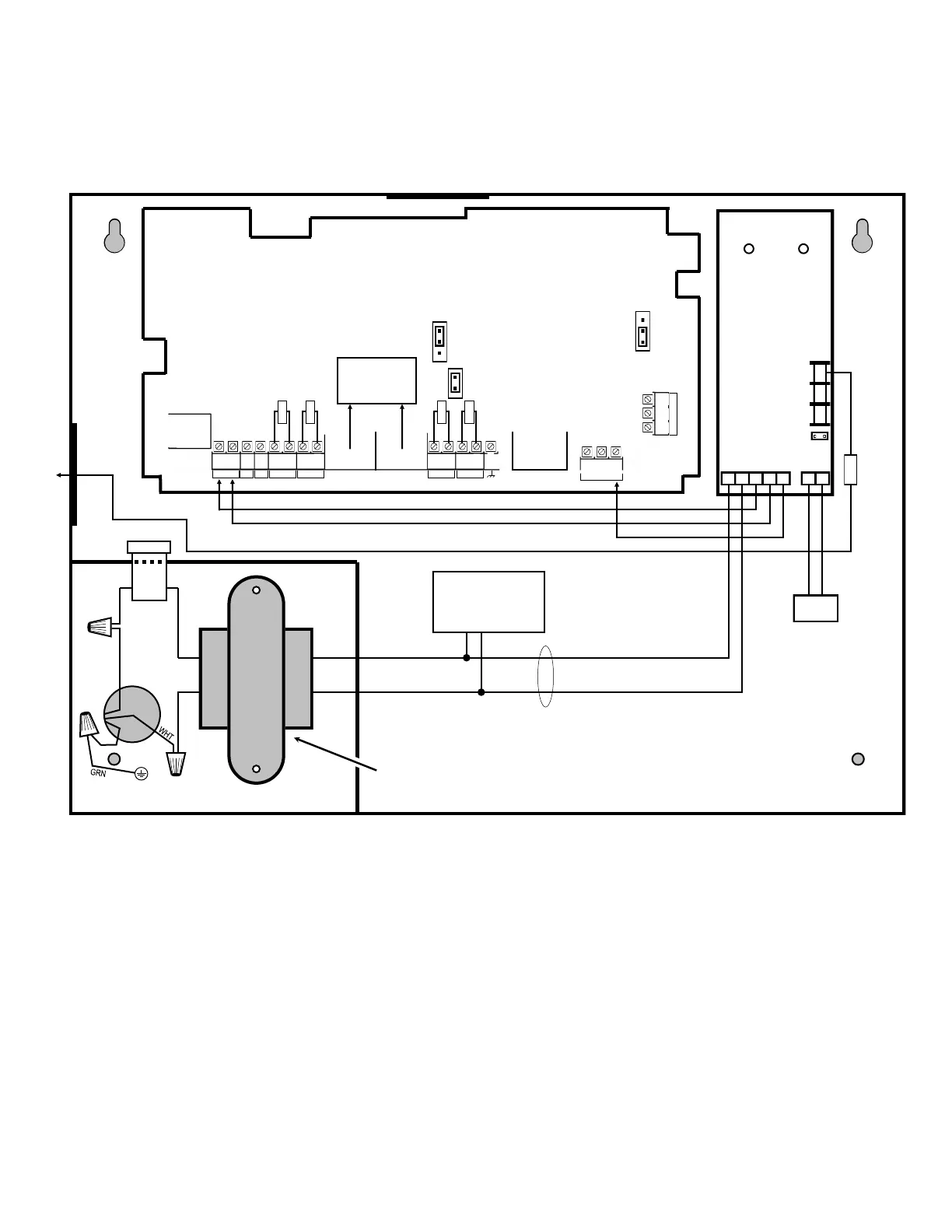
(Commercial Fire) SLE-LTEVI-CFBPS & SLE-LTEAI-CFBPS
Wiring Diagram
SLE-LTEVI-CFBPS & SLE-LTEAI-CFBPS
PC Board
All connections are power limited except AC
Mains and battery terminals
Power Supply
(SLE-ULPS-R)
Yellow
Trouble
LED
Green AC
ON LED
+ BAT –
RED BLK
6 7 2 3 4 5 1
8 9 10
N/C
COM
N/O
Black (‒)
Red (+)
Battery
.5A
Fuse
16.5VAC
Class 2
*Notes:
Connect the StarLink communicator to the control panel output for Telco Trouble (this is the DACT interconnect wiring to the communicator). Remember to
program the StarLink communicator module to report this IN2 Telco Trouble and for line cut (EOLR) to the central station. In addition, always add an EOLR
at the control panel Telco Trouble Output (Fire Aux Relay for the GEMC control panels).
Use EOLR value as specified by the control panel installation instructions.
IN1 not supervised. IN2, IN3, IN4 and IN5 can be supervised.
Licensed electrician required to wire the 120VAC connections to the transformer in accordance with N.E.C. and local code requirements. Refer to section
"SUPPLYING POWER".
Route 120VAC only through the transformer compartment knockouts.
Keep all non-power limited wiring separate from all power-limited wiring inside the housing by 1/4". In addition, maintain a minimum 1/4" separation of all
primary wiring in the transformer compartment from the yellow secondary wires of the transformer.
Remove shunt J2 to isolate relay OUT1 common from ground (i.e. jumper on = wet (circuit common); off = dry contact). When wet, configuration is used; the
power should be derived from the alarm control panel.
J7: Remove shunt to disable 10K EOLR across pins 1 and 8 of primary TELCO input. Do not remove if " Tip/Ring Wiring Fault Report" is enabled.
OUT1 N/C (terminal 21) of the StarLink module must be programmed for any communicator trouble and wired to the FACP trouble input if JP2
shunt is not removed and Telco 2 is not monitored.
The Power Supply Relay Trouble Output must be wired to FACP Zone input dedicated to communicator trouble, unless JP2 is removed and Telco 2 is
monitored. When JP2 is removed and Telco 2 is monitored, the power supply trouble relay should be wired to IN4 with a series resistor to terminal 9
(remove EOLR) and IN4 programmed to report a Power Supply trouble.
IN1 + 12V – AC IN
Note: Maintain
minimum 1/4"
separation of
battery leads from
all other wiring.
EOLR*
J2
Chassis Mounted 16.5VAC / 20VA Transformer
BLK
Note: Maintain minimum 1/4" separation
of all wiring in this compartment from
the yellow wires of the transformer.
Relay con-
tacts rated
max 30VDC,
0.5A
12VDC
output is
power
limited
(Earth Ground)
Note: Connect IN2 to a
panel output used for
identifying Telco line cut (this
is the DACT interconnect
wiring to the radio).
TRF12/T123
16.5V / 20VA
Transformer
or
(To control panel*)
Remove shunt
J2 to isolate relay
OUT1
common from ground (i.e. jumper on =
wet (circuit common); off = dry contact).
JP1
Shunt JP1 on
bottom 2 pins
10kΩ
10kΩ
10kΩ
10kΩ
To FACP Telco
1 & 2 (or Primary
& Secondary)
JP2
Remove JP2 to
enable TELCO2
trouble on
Communicator trouble
J7
 Loading...


