16
W415-0210 / R / 02.27.08
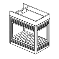
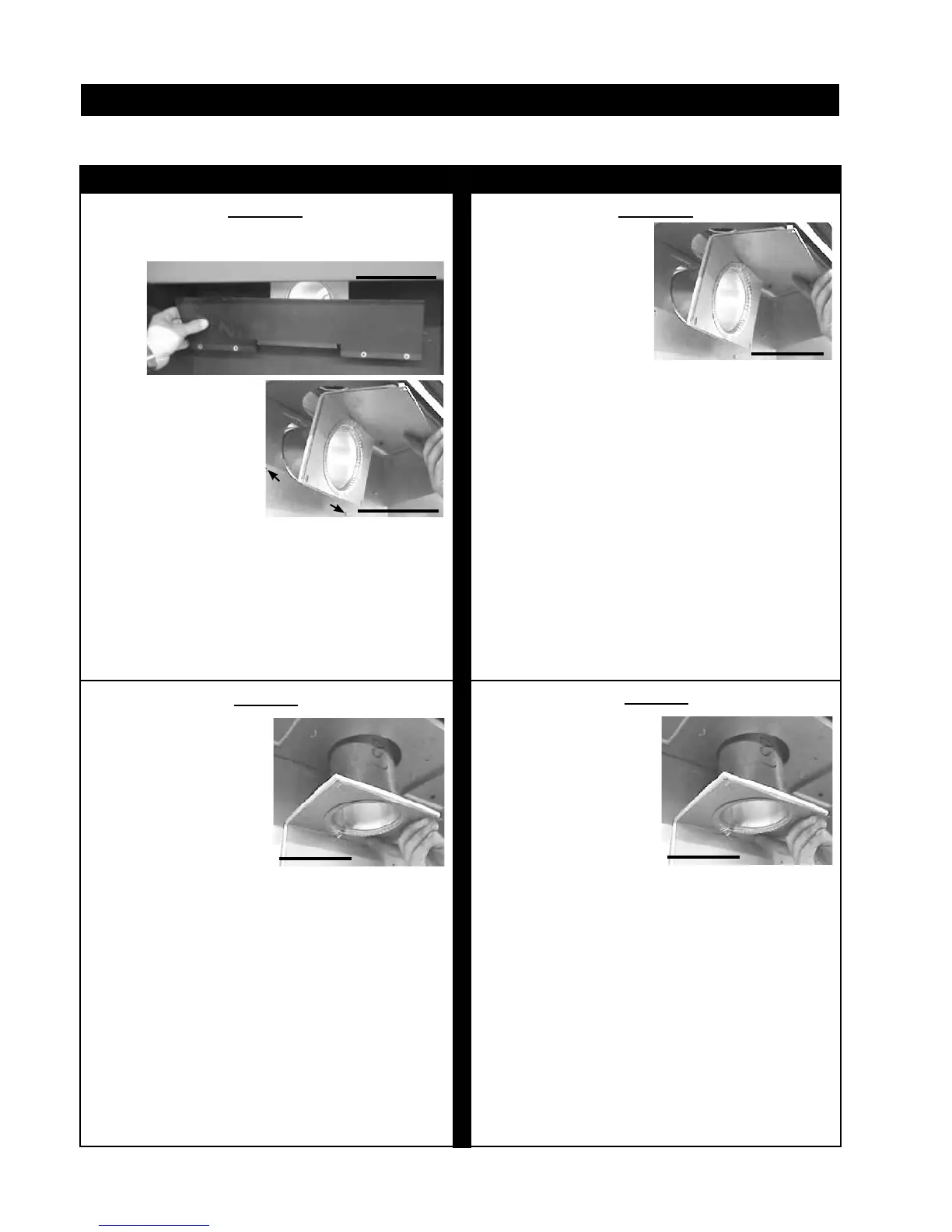
Remove the baffl e from the back of the fi rebox by removing
the four screws. FIGURE 20a.
From inside the firebox,
insert the 4" flue pipe /
gasket assembly (provided)
through the rear of the
fi rebox. Secure the gasket
assembly to the rear and
top of the unit using 4 #8
x ¾ inch Hex Head Wildrill
screws supplied.
Do not overtighten. The gasket needs only to be snug
against the fi rebox. FIGURE 20b.
Before attaching elbows to the collars on the back
of the fi replace, 1½" will need to be trimmed off
the 4" collar.
Re-attach the baffl e to the back of the fi rebox using the four
screws. FIGURE 20a.
FIGURE 21
FAILURE TO INSTALL THE CAP WILL CAUSE THE FIREPLACE TO FUNCTION IMPROPERLY AND
CAN CAUSE INJURY OR PROPERTY DAMAGE.
SEE TOP EXIT PREPARATION FOR DETAILS.
PRE-INSTALLATION PREPARATION
BAFFLE
SCREWS
FIGURE 20b
BAFFLE
FIGURE 20a
Remove the baffle from
the back of the firebox by
removing the four screws.
FIGURE 20.
1. Remove the 7" diameter
cap from the top of the
fi replace and re-secure it over
the 7" collar located at the
rear of the unit. Press fi rmly
on the cap while securing to ensure an airtight seal. Do not
damage the gasket.
2. Remove the plate covering the 4" diameter flue
opening (seen inside the top of the 7" diameter collar) and
discard. Try not to disturb the retaining ring or the gasket
beneath. Re-secure the ring and gasket using the screws
removed from the plate.
3. From inside the fi rebox, insert the 4" fl ue pipe / gasket
assembly through the heat shield and out through the
retaining ring. Secure the assembly to the rear and top of the
unit using 4 #8 x ¾" Hex Head Wildrill screws supplied. Do
not overtighten. The gasket needs only to be snug against
the fi rebox. FIGURE 21.
Re-attach the baffl e to the back of the fi rebox using the four
screws. FIGURE 20A.
GD36
BGD36
From inside the firebox,
insert the 4" flue pipe /
gasket assembly (provided)
through the rear of the
fi rebox. Secure the gasket
assembly to the rear and
top of the unit using 4 #8
x ¾ inch Hex Head Wildrill
screws supplied.
Do not overtighten. The gasket needs only to be snug
against the fi rebox. FIGURE 22.
Before attaching elbows to the collars on the
back of the fi replace, 1½" will need to be trimmed
off the 4" collar.
FIGURE 23
FIGURE 22
1. Remove the 7"
diameter cap from the top
of the fireplace and re-
secure it over the 7" collar
located at the rear of the
unit. Press fi rmly on the cap
while securing to ensure an
airtight seal. Do not damage
the gasket.
2. Remove the plate covering the 4" diameter fl ue
opening (seen inside the top of the 7" diameter collar) and
discard. Try not to disturb the retaining ring or the gasket
beneath. Re-secure the ring and gasket using the screws
removed from the plate.
3. From inside the fi rebox, insert the 4" fl ue pipe /
gasket assembly through the heat shield and out through
the retaining ring. Secure the assembly to the rear and
top of the unit using 4 #8 x ¾" Hex Head Wildrill screws
supplied. Do not overtighten. The gasket needs only to
be snug against the fi rebox. FIGURE 23.
REAR EXIT REAR EXIT
TOP EXIT
TOP EXIT
http://www.northlineexpress.com
 Loading...