17
W415-0210 / R / 02.27.08
HORIZONTAL INSTALLATION
INSTALLATION
WALL AND CEILING PROTECTION
For optimum performance it is recommended that all horizontal runs have a minimum 1" rise per foot using fl exible
venting. For safe and proper operation of the fi replace, follow the venting instructions exactly.
If fl exible venting is to be used remove the rigid fi restop spacer. The remaining
hole is sized for fl exible venting.
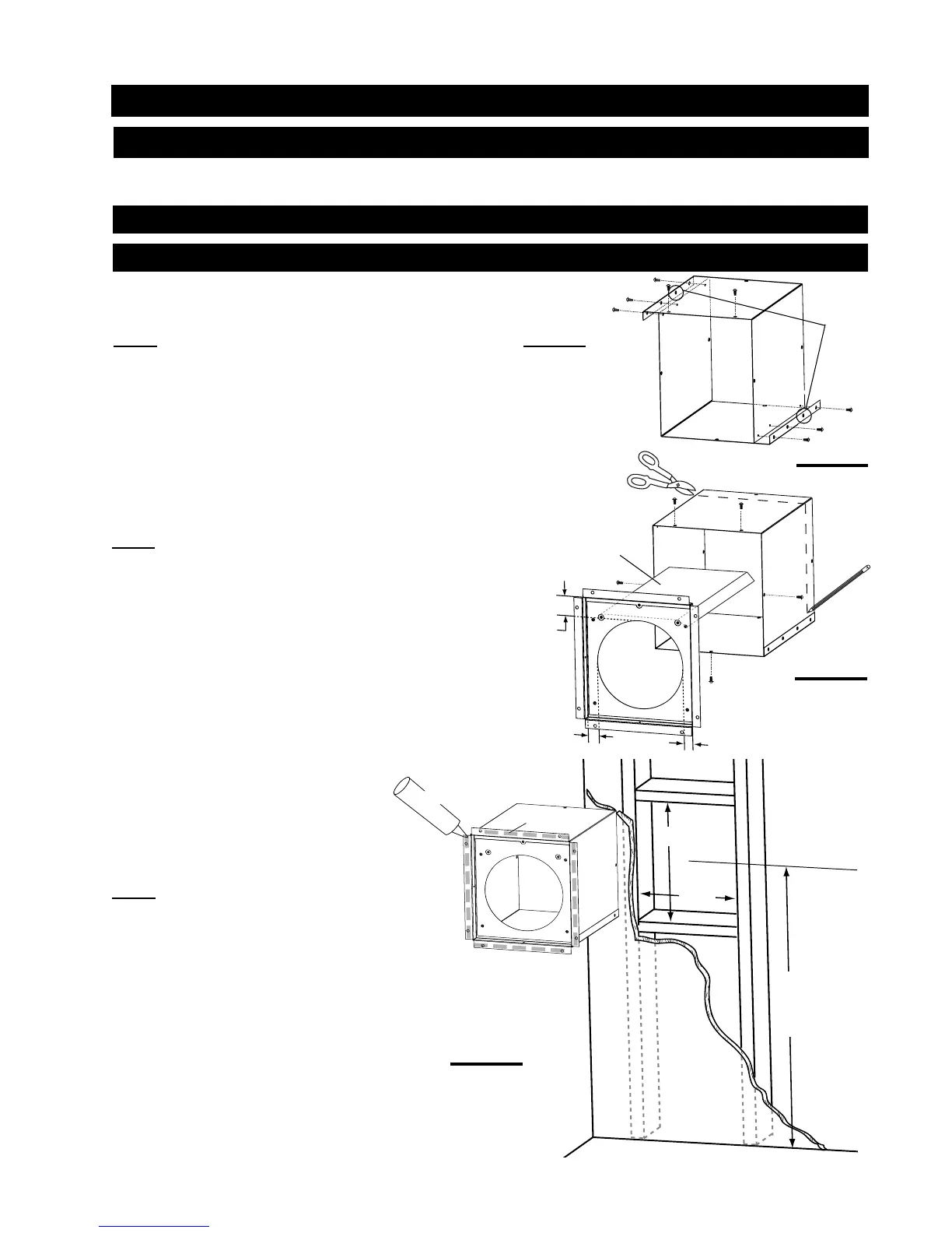
This application occurs when venting through an exterior wall. Having
determined the air terminal location, cut and frame a hole in the
exterior wall 9 7/8" wide by 11 3/8" high to accommodate the fi restop
sleeve assembly.
NOTE: THE FIRESTOP SLEEVE ASSEMBLY MUST BE INSTALLED
WITH THE 2" CLEARANCE TO THE TOP.
The length of the vent shield may be cut shorter for combustible
walls that are less than 8 1/2" thick but the vent shield must extend
the full depth of the combustible wall.
1. Insert the fi restop sleeve assembly into the wall, mark the wall
depth and trim the vent sleeve to suit. The screws that secure the
vent sleeve may need to be repositioned to ensure a rigid assembly
is maintained. Figure 25.
2. Apply a bead of caulking (not supplied) to the inside surface of the
fi restop fl ange and secure the assembly to the wall. (Ensure that the
rectangular shaped assembly is installed
to maintain 2" from the top of the vent).
Figure 26.
3. Once the vent pipe is installed in it's fi nal
position, apply high temperature sealant
W573-0002 (not supplied) between the pipe
and the fi restop.
NOTE: DO NOT FILL THE CAVITY
BETWEEN THE PIPE AND THE
VENT SLEEVE WITH ANY TYPE OF
MATERIAL.
1. Assemble the two halves of the vent sleeve by aligning the holes that come
together to make a rectangular shape (lip to the outside). Secure using 6 of the
screws supplied in the manual baggie.
NOTE: SCREWS NOT REQUIRED IN TWO BLIND HOLES. See Figure 24.
2. Fit the fi restop spacer into one end of the vent sleeve and secure through
the aligned holes on the top, bottom, and sides with the remaining 5 screws
supplied.
GD36 FIRESTOP SLEEVE ASSEMBLY
11
3/8
”
DETERMINE
THE
CORRECT
HEIGHT
FIRESTOP
SLEEVE
ASSEMBLY
FLANGE
CAULKING
9
7/8
”
FIGURE 26
BLIND
HOLES
FIGURE 24
FIGURE 25
2”
1”
1”
TOP
FIRESTOP
SPACER
VENT
SLEEVE
VENT
SHIELD
http://www.northlineexpress.com
 Loading...