:*:nat
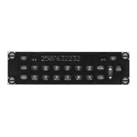
PTAI2-300
POTS Telephone Adapter with NVIS Display
SM55-3 lnstallation
and Operation
Manual
2.4
lnstallation Procedures
2.4.1
Warninqs
WARNING:
High volume settings can
cause
hearing
damage.
Set the headset
volume control to the minimum
volume setting
prior
to conducting
tests, and
slowly
increase
the headset volume
to a comfortable
listening
level.
2.4.2
Cautions
CAUTION:
Do
not take a
ground
from the instrument
panel
or similar
location that
shares a
ground
return with
a turn
and bank,
horizon
or other motor driven instrument. This may
cause
the
PTA12-300
unit to
pick
up
the
sound of the motor as
ground
loop interference.
2.4.3
Cablins and Wirinq
All wire
shall be selected in
accordance with the original aircraft manufacturer's Maintenance lnstructions
orAC43.13-1B
Change 1, Paragraphs
1l-76 through 11-78. Unshielded wire types shallqualifyto
MIL-W-22759
as
specified in 4C43.13-18
Change
l, Paragraphs 11-85, 11-86,
and listed in Table 11-11
For
shielded wire applications,
use Tefzel MIL-C-27500
shielded wire
with
solder sleeves
(for
shield
terminations)
to make the
most compact
and
easily terminated interconnect. Follow
the connector map in
Section 2.7
as
required.
Allow
3" from the end
of the shielded wiring to the
shield
termination
to allow
the connector
hood to be
easily installed.
Reference the interconnect
drawing in Section 2.7 fo¡
shield
termination
details.
Maintain
wire
segregation and route wiring in
accordance
with
the original aircraft manufacturers
Maintenance
lnstructions.
Unless othen¡¡ise noted,
all wiring
shall be a
minimum
of
22 AWG,
except
power
and
ground
lines, which
shall be a minimum
of
20
AWG. Reference
the
lnterconnect
drawing for additional specifications. Check
that
the
ground
connection is
clean and well
secured,
and that it
shares no
path
with
any electrically noisy
aircraft
accessories such as blowers, turn
and bank
instruments
or similar loads.
2.4.4
Post-lnstallation
Ghecks
2.4.4.1
Voltaqe/Resistance
Checks
Do
not
attach the
PTA12-300
until the following conditions are met.
Check
the following:
a)
Check
P101,
pin
<1>
for
+28
Vdc relative to
ground.
b) Check
Pí01,
pin
<3>
for
+28
Vdc OR
pin
<4>
lor
+5
Vdc relative to
ground.
c)
Check
P101
,
pins
<14>, <16>
and
<19>
for continuity to
ground (less
than
0.5O).
Section
2 Rev: 1.01
lssue
4
Page
2-2
ENG-FORM:805-0121 DoT
CONFIDENTIAL AND PROPRIETARY
TO NORTHERN AIRBORNE TECHNOLOGY LTD.
The document reference is online, please check the correspondence between the online documentation and the printed version.