2. Remove the power connector from the cRIO-9068.
Caution Do not tighten or loosen the terminal screws on the power connector
while the cRIO-9068 is powered on.
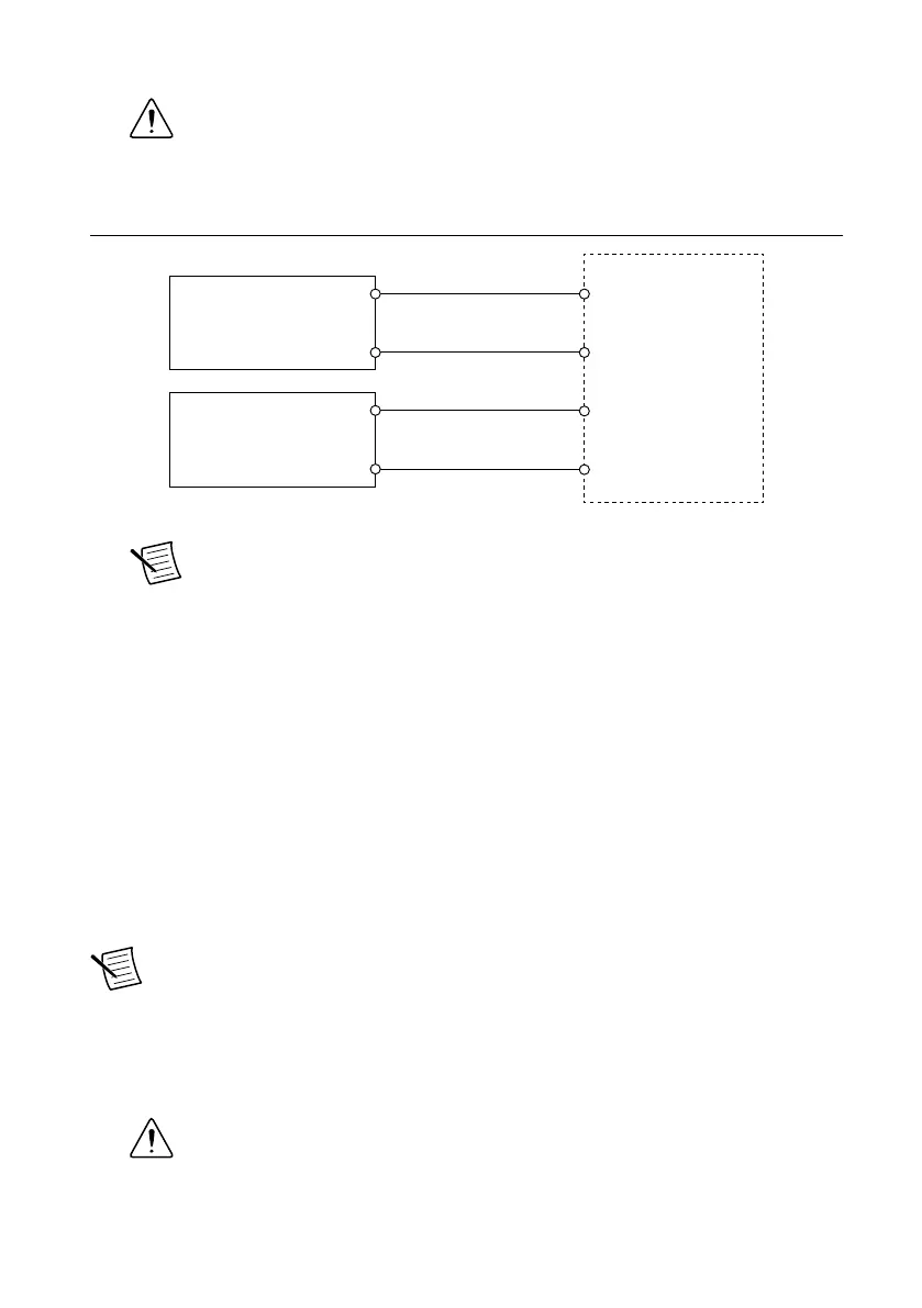
3. Connect the primary power supply and optional secondary power supply to the power
connector, as shown in the following figure.
Figure 3. cRIO-9068 Power Connections
Power Connector
V2
C
C
V1
Primary Power Supply
+
–
–
+
Secondary Power Supply
Note The C terminals are internally connected to each other.
4. Tighten the terminal screws on the power connector to 0.20 N · m to 0.25 N · m
(1.8 lb · in. to 2.2 lb · in.) of torque.
5. Install the power connector on the front panel of the cRIO-9068.
6. Tighten the power connector screw flanges to 0.20 N · m to 0.25 N · m (1.8 lb · in. to
2.2 lb · in.) of torque.
7. Power on the primary power supply and optional secondary power supply.
Connecting the cRIO-9068 to the Host Computer or
Network
Complete the following steps to connect the cRIO-9068 to a host computer or Ethernet
network using the RJ-45 Ethernet port 1. NI recommends using the RJ-45 Ethernet port 1 for
communication with deployed systems.
Note You can configure the RJ-45 Ethernet port 2 in Measurement & Automation
Explorer (MAX) under the Network Settings tab.
1. Power on the host computer or Ethernet hub.
2. Connect the RJ-45 Gigabit Ethernet port 1 on the cRIO-9068 to the host computer or
Ethernet hub using a standard Category 5 (CAT-5) or better shielded, twisted-pair
Ethernet cable.
Caution To prevent data loss and to maintain the integrity of your Ethernet
installation, do not use a cable longer than 100 m (328 ft).
8 | ni.com | cRIO-9068 Getting Started Guide
 Loading...