EasyManua.ls Logo

National Instruments PXIe-1088 - User Manual

National Instruments PXIe-1088
26 pages
Print Icon
To Next Page IconTo Next Page
Loading...
USER GUIDE
PXIe-1088
This document describes the features of the PXIe-1088 chassis and contains information about
configuring the chassis, installing the modules, and operating the chassis.
Contents
Related Documentation ............................................................................................................2
Getting Started.......................................................................................................................... 2
Unpacking......................................................................................................................... 2
What You Need to Get Started..........................................................................................2
Key Features..................................................................................................................... 3
Chassis Components......................................................................................................... 4
Optional Equipment.......................................................................................................... 5
PXIe-1088 Backplane Overview.............................................................................................. 6
Interoperability with CompactPCI.................................................................................... 6
System Controller Slot...................................................................................................... 6
Hybrid Peripheral Slots.....................................................................................................6
PXI Local Bus...................................................................................................................7
PXI Trigger Bus................................................................................................................ 8
System Reference Clock................................................................................................... 8
Installation and Configuration.................................................................................................. 9
Safety Information............................................................................................................ 9
Chassis Cooling Considerations......................................................................................10
Rack Mounting................................................................................................................13
Connecting the Safety Ground........................................................................................14
Connecting to a Power Source........................................................................................ 15
Installing a System Controller.........................................................................................15
Installing Peripheral Modules......................................................................................... 16
LED Indicator................................................................................................................. 17
DIP Switches...................................................................................................................18
Inhibit Mode....................................................................................................................19
Fan Mode........................................................................................................................ 19
PXI Express System Configuration with MAX..............................................................20
Using System Configuration and Initialization Files......................................................24
Maintenance............................................................................................................................ 25
Service Interval............................................................................................................... 25
Preparation...................................................................................................................... 25
Cleaning.......................................................................................................................... 25
Worldwide Support and Services............................................................................................ 26
Question and Answer IconNeed help?

Do you have a question about the National Instruments PXIe-1088 and is the answer not in the manual?

Summary

Related Documentation

Getting Started

Unpacking the Chassis

Procedures for inspecting the shipping container and chassis for damage during unpacking.

Required Items for Setup

Lists the items included in the PXIe-1088 chassis kit and required accessories.

PXIe-1088 Key Features

High Performance Capabilities

Details bandwidth, slot connectivity, cooling, and clock specifications for high performance.

High Reliability Features

Lists features contributing to high reliability, such as temperature range and monitoring.

Optional Chassis Features

Chassis Accessories and Services

Details optional rack-mount kits, filler panels, slot blockers, installation services, and handle/feet kits.

Optional Chassis Equipment

Chassis Add-ons and Kits

Lists optional EMC filler panels, slot blockers, handle/feet kit, rack mount kits, and fan kits.

PXIe-1088 Backplane Overview

CompactPCI Interoperability

Discusses compatibility with various CompactPCI and PXI Express devices.

System Controller Slot Details

Details the system controller slot and its role in system configuration.

Hybrid Peripheral Slot Functionality

Describes the eight hybrid peripheral slots and their capabilities.

PXI Local Bus Connectivity

PXI Trigger Bus Functionality

System Reference Clock Signals

Installation and Configuration Guide

Critical Safety Precautions

Crucial safety warnings regarding electrical hazards, grounding, live circuits, explosive atmospheres, and part replacement.

Chassis Cooling and Clearance

Ensuring Adequate Cooling Clearance

Instructions on maintaining sufficient clearance for proper airflow and cooling.

Chassis Ambient Temperature Definition

Setting Chassis Fan Speed

Installing Filler Panels

Installing Slot Blockers

Chassis Rack Mounting

Connecting Chassis Safety Ground

Safety Grounding Procedure

Step-by-step instructions for connecting the chassis to an earth safety ground.

Connecting to Power Source

Power-On Test Procedure

Procedure for testing power functionality using the Power Inhibit switch.

Installing a System Controller

System Controller Installation Steps

Detailed steps for installing a PXI Express system controller into the chassis.

Installing Peripheral Modules

Peripheral Module Installation Steps

General instructions for installing peripheral modules into the chassis slots.

Front Panel LED Indicator

Backplane DIP Switch Functions

Chassis Power and Fan Control

Inhibit Mode Operation and Selection

Details the chassis inhibit modes and their selection via DIP switch for power control.

Fan Mode and Cooling Profiles

Explains fan modes (Auto, High) and cooling profiles (38W, 58W) for thermal management.

PXI Express System Configuration with MAX

Trigger Configuration in MAX

PXI Trigger Bus Routing in MAX

PXI Trigger Bus Routing in MAX

Fan Configuration in MAX

System Configuration and Initialization Files

Chassis Maintenance Procedures

Recommended Service Interval

Guidance on cleaning frequency based on operating environment.

Maintenance Preparation and ESD

Precautions for qualified personnel performing maintenance, including ESD.

Chassis Cleaning Procedures

Procedures for cleaning the chassis exterior, interior, and fan filters.

Interior Chassis Cleaning

Exterior Chassis Cleaning

Worldwide Support and Services

Overview

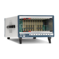
The PXIe-1088 is a high-performance 9-slot PXI Express chassis designed for a wide range of instrumentation applications. It integrates a robust backplane and power supply within a structurally optimized design, fully complying with the PXI-5 PXI Express Hardware Specification. This chassis offers significant flexibility, supporting various PXI Express, CompactPCI Express, and modified PXI/CompactPCI peripheral devices within a single unit.

Function Description

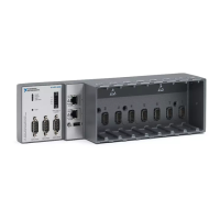
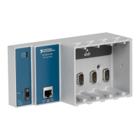
The PXIe-1088 chassis serves as a foundational platform for PXI Express systems, providing the necessary infrastructure for system controllers and peripheral modules. Its backplane facilitates high-speed data transfer and synchronization between modules. The chassis includes a dedicated system controller slot (slot 1) configured for 4-Link CompactPCI Express and PXI Express system controllers, with three expansion slots for wider controller modules. This design prevents system controllers from occupying valuable peripheral slots.

The backplane intelligently routes PCI Express links from the system slot to the peripheral slots. Specifically, three peripheral slots (4, 6, and 8) receive x4 links, while five other peripheral slots connect via x1 links through a PCI Express switch, which itself links to the system slot via an x4 connection. This architecture ensures high dedicated bandwidth for each PXI Express slot, supporting up to 500 MB/s or 2 GB/s (single direction) per slot for Gen-2 PCI Express.

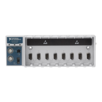
The chassis also features eight hybrid peripheral slots (slots 2 through 9), which are versatile enough to accept PXI Express peripherals with x8, x4, or x1 PCI Express links, CompactPCI Express Type-2 peripherals, and hybrid-compatible PXI or CompactPCI 32-bit peripherals. These hybrid slots offer full PXI Express and 32-bit PXI functionality, with specific connectivity to PXI Local Bus 6.

For synchronization, the PXIe-1088 provides a low-jitter internal 10 MHz reference clock for PXI/PXI Express slots and a 100 MHz reference clock for PXI Express slots, both with high stability. It also supplies PXIe_SYNC100 to each peripheral slot, with independent drivers for all reference clock signals to ensure minimal skew.

The PXI Trigger Bus, comprising eight trigger lines per bus segment, enables synchronized operation of multiple PXI peripheral modules. Trigger lines can be routed across trigger bridges in either direction, allowing for system-wide trigger signal distribution. Static and dynamic trigger routing can be configured through software, preventing double-driving of trigger lines.

Usage Features

The PXIe-1088 is designed for ease of use and high reliability in various operating conditions. It supports a wide operating temperature range and incorporates features for power supply, temperature, and fan monitoring to ensure stable operation.

The chassis offers two main fan operating modes: Auto and High. In Auto mode, fan speeds adjust based on chassis intake air temperature, optimizing acoustic performance. In High mode, fans operate at maximum speed for superior cooling, regardless of temperature. These modes are available for both 38 W and 58 W cooling profiles, accommodating different module power dissipations. Fan mode selection can be managed via a DIP switch on the backplane or through the Measurement & Automation Explorer (MAX) software.

The PXIe-1088 also supports two inhibit modes: Default and Manual. In Default mode, the power inhibit button functions normally, allowing users to power on/off the chassis, even without a system controller installed. In Manual mode, the chassis powers up automatically when AC power is applied and shuts down when AC power is removed. This mode is selected via a DIP switch.

Installation of system controllers and peripheral modules is straightforward, involving sliding the module into card guides and securing it with mounting screws. The chassis includes an LED indicator on the front panel to display its status: steady green for normal operation and steady red for out-of-range temperature or internal fault.

For optimal thermal performance, the chassis requires adequate clearance around its intake and exhaust vents. Filler panels are provided for unused slots to maintain proper cooling, and optional slot blockers can further enhance thermal management. Rack mounting is supported with optional kits, and the chassis feet are removable for this purpose.

The PXI Platform Services software, included with the chassis, automatically identifies system components and generates configuration files. MAX provides a comprehensive interface for configuring the PXI system, monitoring chassis information such as voltages, temperatures, fan speeds, and performing self-tests and firmware updates. It also allows for detailed trigger configuration, including static reservation and dynamic routing, to prevent conflicts and potential damage to devices.

Maintenance Features

The PXIe-1088 is designed with maintenance in mind to ensure long-term reliability. Key maintenance aspects include:

  • Periodic Cleaning: Regular cleaning of the chassis exterior and interior is recommended based on the operating environment to prevent dust accumulation and increase reliability.
  • Fan Maintenance: The chassis features field-replaceable fans, simplifying maintenance and ensuring continuous optimal cooling.
  • Cleaning Procedures: Exterior surfaces can be cleaned with a dry, lint-free cloth or soft-bristle brush, or a cloth moistened with a mild soap solution. Interior cleaning involves using a dry, low-velocity stream of air and a soft-bristle brush around components. Users are cautioned to avoid moisture inside the chassis, especially near vents and connectors, and to refrain from using harsh chemical cleaning agents.
  • Safety Precautions: Before any servicing, the power cable must be disconnected. Service personnel are advised to read the safety information provided in the manual and to perform maintenance in a static-free environment, wearing a grounded wrist strap to protect static-sensitive components.
  • Part Replacement: Only exact electrical and mechanical replacement parts should be used for servicing to avoid harm to personnel or damage to the chassis. Users are directed to contact National Instruments for replacement part information.
  • No Modifications: Users are explicitly warned against modifying any part of the chassis from its original condition, as unsuitable modifications can lead to safety hazards.

National Instruments PXIe-1088 Specifications

General IconGeneral
Number of Slots18
PXI Express Slots8
System Timing Slot1
Power SupplyAC
Ethernet Ports1
USB Ports2
Storage Temperature-40 to 70 °C
Form FactorPXI Express
Chassis Size3U
Slot TypesPXI Express
CoolingForced air
BackplanePXI Express
Operating Temperature0 °C to 55 °C
Relative Humidity Range10 to 90% (noncondensing)

Related product manuals