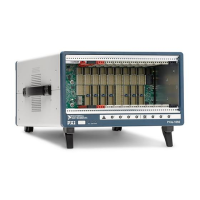
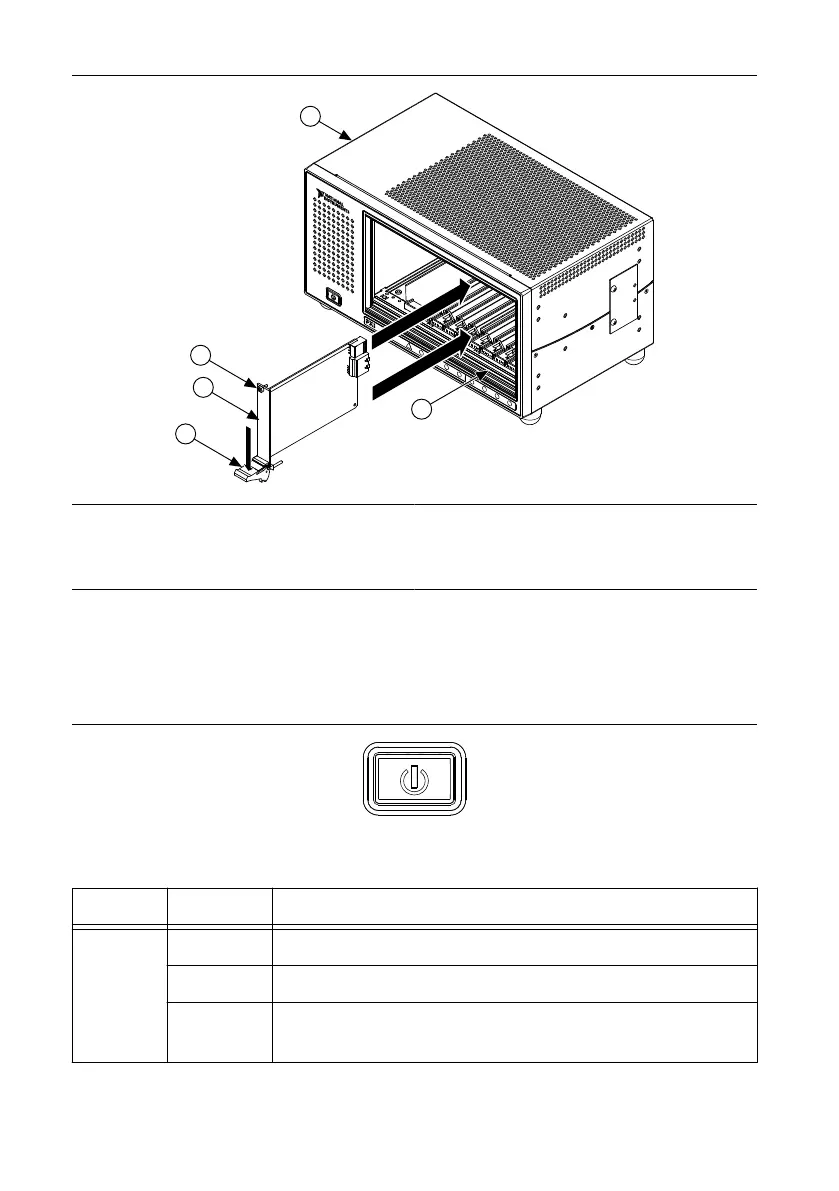
Figure 10. Installing PXI, PXI Express, or CompactPCI Peripheral Modules
8
9
7
6
5
4
3
2
H
H
H
H
H
H
H
H
1
LOW POWER
PXIe-1088
3
2
1
4
5
1. Injector/Ejector Handle
2. PXI Peripheral Module
3. Peripheral Module Front Panel Mounting Screws
(2x)
4. PXI Express Chassis
5. Injector/Ejector Rail
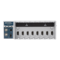
LED Indicator
The following figure shows the front panel Status LED. The following table describes the
Status LED states.
Figure 11. Status LED
Table 2. Front Panel Status LED States
LED State Description
Status LED
Off Chassis is powered off.
Steady green Chassis is powered on, and operating normally.
Steady red
Indicates temperature is out of range, or an internal chassis fault
has occurred.
PXIe-1088 User Guide | © National Instruments | 17

 Loading...