Appendix B Timing Diagrams
© National Instruments Corporation B-37 M Series User Manual
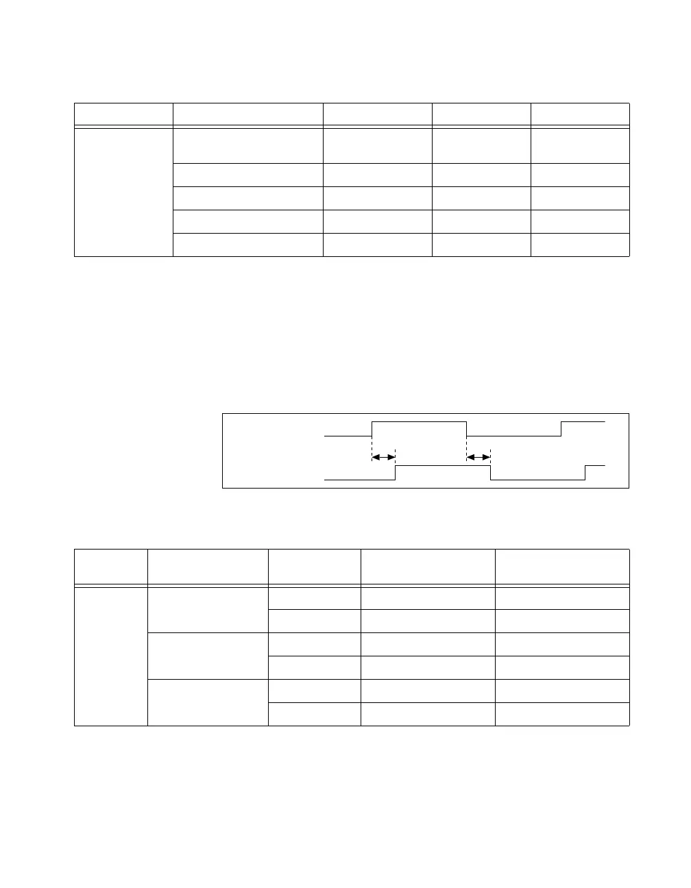
Count Enable Delay
Table B-29 shows timing for the internal Count Enable signal, as shown in
Figure B-41. Count Enable enables the 32-bit counter to count on the rising
edge of the Selected Source signal.
The delays depend on both the synchronization mode and gating mode for
the application.
Figure B-45. Count Enable Delays
Table B-28. Selected Source Delays Timing
Time From To Min (ns) Max (ns)
t
3
PFI_i, RTSI_i, PXI_STAR_i,
or any internal signal
Selected Source 8.0 21.0
20 MHz Timebase Selected Source 1.5 4.0
100 kHz Timebase Selected Source 1.5 4.0
80 MHz Timebase Selected Source 1.0 2.5
PXI_CLK10 Selected Source 1.0 3.5
Table B-29. Selected Gate to Count Enable Delays
Time
Synchronization
Mode
Gating Mode Min (ns) Max (ns)
t
4
80 MHz Source Edge 0.5 5.0
Level –1.0 0.5
Other Internal Source Edge 1/2 Source Period – 1 ns 1/2 Source Period + 3 ns
Level 1/2 Source Period – 2.5 ns 1/2 Source Period – 1 ns
External Source Edge 7.5 22.0
Level 6.0 18.0
t
4
t
4
Selected_Gate
Count_Enable
 Loading...