Do you have a question about the National Instruments PCI-6251 and is the answer not in the manual?
Precautions for working with voltages above 42.4 Vpk or 60 VDC.
Guidelines for ensuring the product complies with EMC regulations.
Steps for installing the NI-DAQmx driver software.
Initiating self-calibration using MAX or programmatically.
Situations where connecting the disk drive power connector is necessary.
Requirements for connecting the USB device chassis to earth ground for EMC.
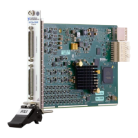
Overview of the main components of an M Series DAQ device.
Description of available 68-pin cables and accessories for M Series devices.
Explanation of how calibration constants are stored and modified.
Overview of SCXI as a signal conditioning system for M Series devices.
Details on Analog Input Channels and their configurations.
Information on the fuse protecting the +5 V terminal from overcurrent.
Table showing LED behavior based on USB device state.
Explanation of Differential, Referenced Single-Ended, and Non-Referenced Single-Ended modes.
How input range affects resolution and accuracy for AI channels.
Acquisition controlled by hardware signals like AI Sample Clock.
Overview of Start, Reference, and Pause triggers for AI.
What floating signal sources are and how to connect them.
How AO offset and reference selection determine the output voltage range.
Using lowpass filters to remove normal output signal glitches.
Generations controlled by hardware signals for precise timing.
Overview of Start and Pause triggers for AO operations.
Using DIO lines as static digital input or output.
DI Sample Clock signal for sampling DIO lines.
DO Sample Clock signal for updating DO terminals.
Precautions to avoid overvoltage, undervoltage, and overcurrent conditions.
Counting rising or falling edges on the Source input.
Measuring the width of high or low pulses on the Gate input.
Measuring the period between two rising or falling edges of the Gate input.
Methods for measuring signal frequency using counters.
Performing position measurements using quadrature or two-pulse encoders.
Outputting a single pulse with specified delay and width.
Generating a train of pulses with programmable frequency and duty cycle.
Signal that increments or decrements the counter value.
Ensuring correct data with slow or non-periodic external sources.
Methods for synchronizing signals to the counter.
Routing external timing signals to M Series functions via PFI.
Enabling programmable debouncing filters on PFI signals.
Overview of the clock routing circuitry in M Series devices.
Methods for synchronizing PXI/PXI Express and PCI/PCI Express devices.
RTSI connector pinout and usage for PCI/PCI Express devices.
Primary methods for data transfer across the PCI bus (DMA, IRQ, Programmed I/O).
Methods for data transfer over USB (USB Signal Stream, Programmed I/O).
Information on PXI clock and trigger signals available on PXI devices.
Generating triggers based on rising or falling edges of digital signals.
Using analog input channels as trigger sources for the NI-PGIA.
Detecting signals below or above a specified level.
Using hysteresis to reduce false triggers due to noise or jitter.
Tips for improving analog trigger accuracy, like using AI channels.
Pinout diagrams and specifications for the NI 6220 device.
Pinout diagrams and specifications for the NI 6221 (68-pin) device.
Pinout diagrams and specifications for the USB-6221 Screw Terminal device.
Top panel and pinout diagrams for the USB-6221 BNC device.
Timing for external signals used as clocks or triggers in AI.
Timing of exported signals to external terminals from analog output.
Delays and requirements for digital waveform acquisitions and generations.
Timing delays for counter/timer circuit inputs and outputs.
Troubleshooting crosstalk, ghost voltages, and random readings in AI.
Minimizing glitches on the analog output signal.
Troubleshooting buffered counter measurement behavior and signal connections.
Troubleshooting device detection issues with MAX or Windows.
How to find and use NI-DAQmx example programs.
References to M Series device specifications and user guides.
Information on NI-DAQmx support and installation for Linux devices.
Resources for learning and using LabVIEW with NI-DAQmx.
Overview of NI services including maintenance, calibration, and system integration.
Information on NI training and certification programs.
Resources for technical support, including KnowledgeBase and forums.
| Product Name | PCI-6251 |
|---|---|
| Manufacturer | National Instruments |
| Category | I/O Systems |
| Bus Type | PCI |
| Analog Input Channels | 16 |
| Analog Input Resolution | 16 bits |
| Analog Output Channels | 2 |
| Analog Output Resolution | 16 bits |
| Digital I/O Channels | 24 |
| Counter/Timers | 2 |
| Operating System Compatibility | Windows, Linux |
| Digital I/O Voltage | 5 V |
| Sampling Rate | 1.25 MS/s |
| Input Voltage Range | ±0.2 V to ±10 V |