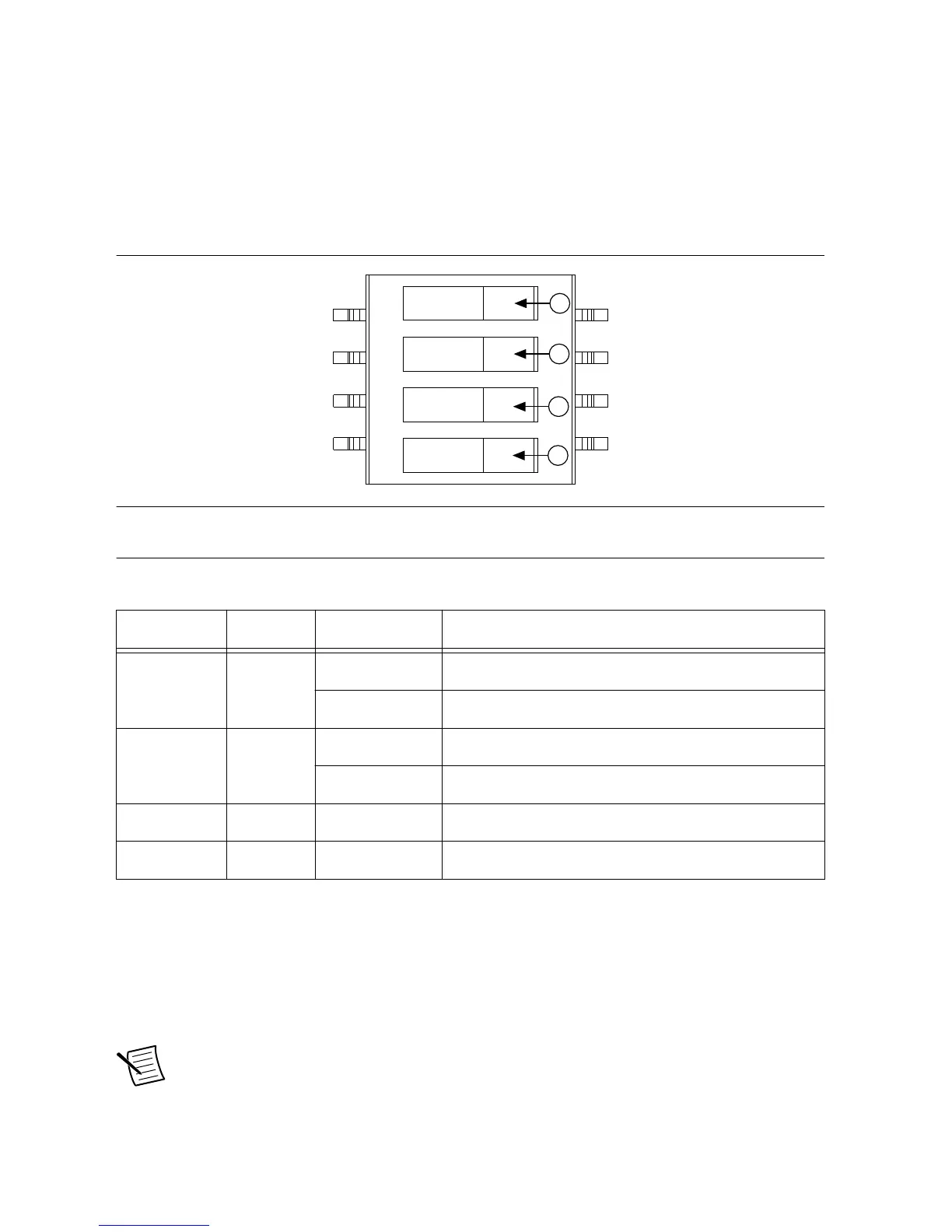
DIP switch #1 (first from the bottom) controls the chassis fan mode. When this switch is in the
off (right) position, Auto mode is selected. When this switch is in the on (left) position, High
mode is selected.
DIP switch #2 (second from the bottom) controls the chassis Inhibit Mode. When this switch is
in the off (right) position, Default mode is selected. When this switch is in the on (left)
position, Manual mode is selected.
Figure 14. Backplane DIP Switches
1 FAN Off (Right) Sets chassis Fan Mode to Auto.
On (Left) Sets chassis Fan Mode to High.
2 PWR Off (Right) Sets chassis Inhibit Mode to Default.
On (Left) Sets chassis Inhibit Mode to Manual.
3 NC — —
4 NC — —
Inhibit Mode
The PXIe-1092 chassis supports operation in two inhibit modes. Default mode is used when
normal power inhibit button functionality is desired. In Default mode, when a system
controller is installed in slot 1 of the chassis, the user can press the power inhibit button to
power on the chassis.
Note In Default mode, you can also power on the chassis without a system
controller installed in slot 1. To power on the chassis from standby, press and hold
PXIe-1092 User Guide | © National Instruments | 23
 Loading...