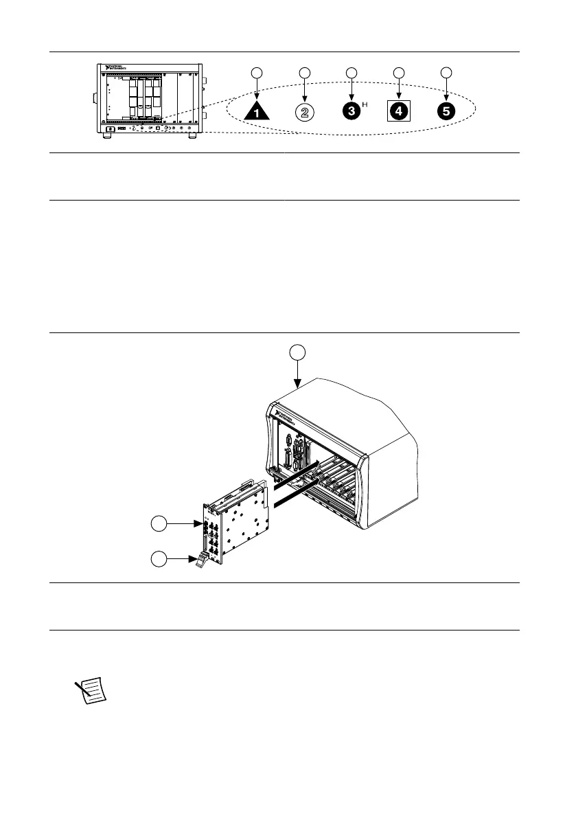
Figure 2. Chassis Compatibility Symbols
1. PXI Express System Controller Slot
2. PXI Peripheral Slot
3. PXI Express Hybrid Peripheral Slot
4. PXI Express System Timing Slot
5. PXI Express Peripheral Slot
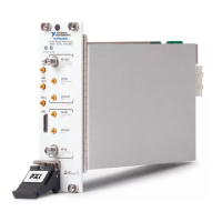
The PXIe-5841 can be placed in PXI Express peripheral slots, PXI Express Hybrid
peripheral slots, or PXI Express system timing slots.
8. Touch any metal part of the chassis to discharge static electricity.
9. Ensure that the ejector handle is in the unlatched (downward) position.
10. Hold the module by the edges and slide it into the empty compatible slots. Ensure the
base engages with the guides in the chassis.
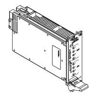
Figure 3. PXIe-5841 Module Installation
1
2
3
ESD
SENSITIVE
N
I P
X
I
e
-
5
6
4
6
R
V
e
c
t
o
r
Si
g
n
a
l
T
r
a
n
s
c
e
i
v
e
r
6
5
M
H
z -
6
.
0
G
H
z, 200 MHz BW
1. PXI Express Chassis
2. PXIe-5841 Module
3. Ejector Handle in Unlatched (Downward) Position
11. Latch the module in place by pulling up on the ejector handle.
12. Secure the module front panel to the chassis using the front-panel mounting screws.
Note Tightening the top and bottom mounting screws increases mechanical
stability and also electrically connects the front panel to the chassis, which can
improve the signal quality and electromagnetic performance.
PXIe-5841 Getting Started Guide | © National Instruments | 7
 Loading...