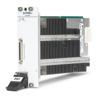
Figure 1. Chassis Compatibility Symbols
1. PXI Express System Controller Slot
2. PXI Peripheral Slot
3. PXI Express Hybrid Peripheral Slot
4. PXI Express System Timing Slot
5. PXI Express Peripheral Slot
6. Touch any metal part of the chassis to discharge static electricity.
7. Place the module edges into the module guides at the top and bottom of the chassis. Slide
the module into the slots until it is fully inserted.
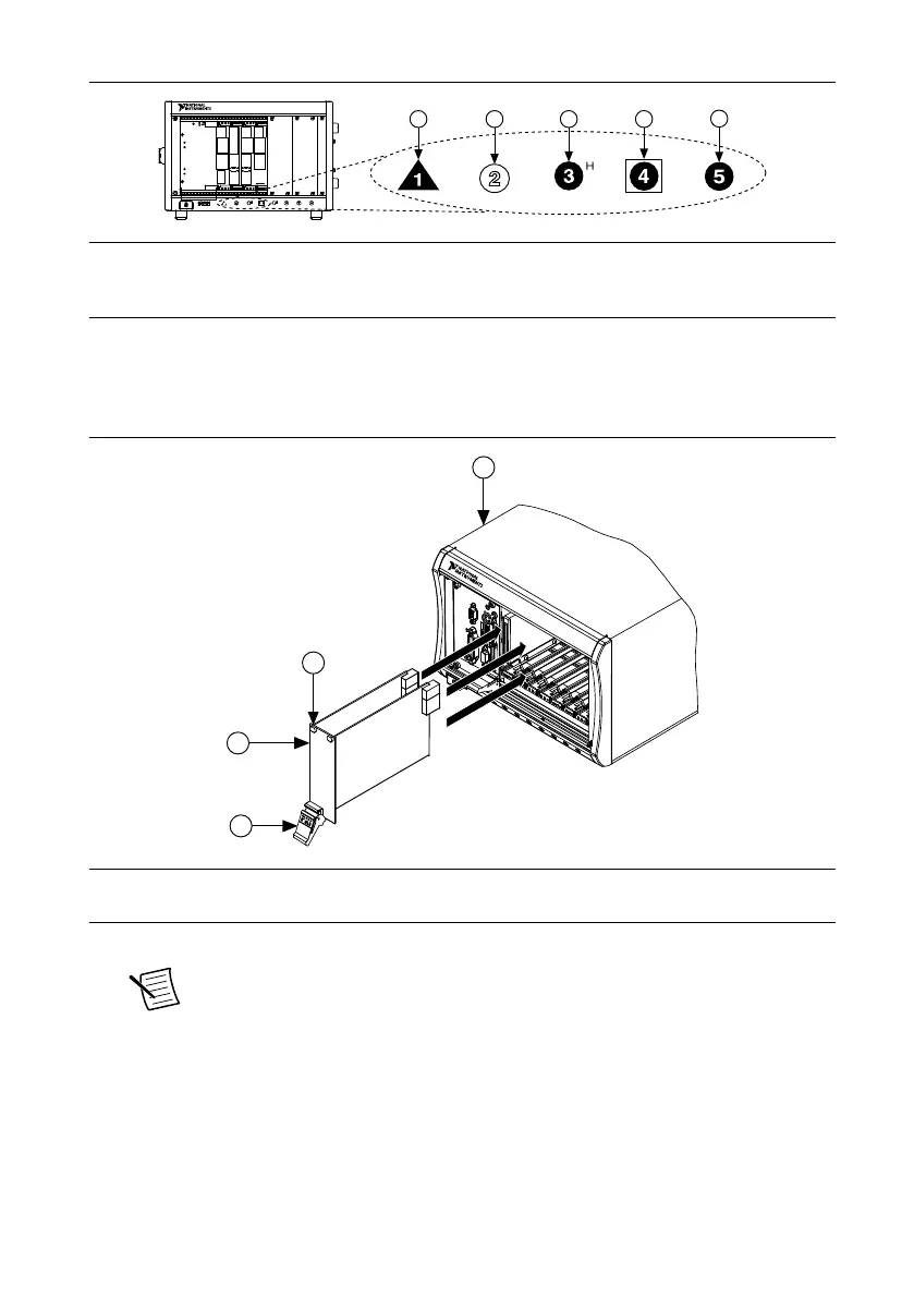
Figure 2. PXIe-6570 Installation
1. PXI Express Chassis
2. Ejector Handle in Down Position
3. NI PXI Express Two-Slot Module
4. Captive Screw
8. Secure the module front panel to the chassis using the front-panel mounting screws.
Note Tightening the top and bottom mounting screws increases mechanical
stability and also electrically connects the front panel to the chassis, which can
improve the signal quality and electromagnetic performance.
9. Cover all empty slots using EMC filler panels or fill using slot blockers to maximize
cooling air flow, depending on your application.
10. Power on the chassis.
6 | ni.com | PXIe-6570 Getting Started Guide
 Loading...