EasyManuals Logo

National Instruments PXIe-6570 Getting Started Guide

National Instruments PXIe-6570
16 pages
To Next Page IconTo Next Page
To Previous Page IconTo Previous Page
Page #7 background imageLoading...
Page #7 background image
Connecting Signals
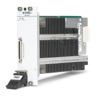
PXIe-6570 Front Panel
The PXIe-6570 front panel has a single 68-pin VHDCI Digital Data and Control (DDC)
connector. The following figure shows the front panel and pinout of the PXIe-6570 digital
pattern instrument.
Figure 3. PXIe-6570 Front Panel
34
33
32
31
30
29
28
27
26
25
24
23
22
21
20
19
18
17
16
15
14
13
12
11
10
9
8
7
6
5
4
3
2
1
68
67
66
65
64
63
62
61
60
59
58
57
56
55
54
53
52
51
50
49
48
47
46
45
44
43
42
41
40
39
38
37
36
35
GND
CAL FORCE
GND
DIO 0
CAL GND, DGS
DIO 2
GND
DIO 4
RESERVED
DIO 6
GND
DIO 8
GND
DIO 10
GND
DIO 12
GND
DIO 14
GND
DIO 16
GND
DIO 18
GND
DIO 20
GND
DIO 22
GND
DIO 24
GND
DIO 26
GND
DIO 28
GND
DIO 30
GND
CAL SENSE
GND
DIO 1
RESERVED
DIO 3
GND
DIO 5
CAL MEASURE
DIO 7
GND
DIO 9
GND
DIO 11
GND
DIO 13
GND
DIO 15
GND
DIO 17
GND
DIO 19
GND
DIO 21
GND
DIO 23
GND
DIO 25
GND
DIO 27
GND
DIO 29
GND
DIO 31
PXIe-6570 Getting Started Guide | © National Instruments | 7

Other manuals for National Instruments PXIe-6570

Questions and Answers:

Question and Answer IconNeed help?

Do you have a question about the National Instruments PXIe-6570 and is the answer not in the manual?

National Instruments PXIe-6570 Specifications

General IconGeneral
BrandNational Instruments
ModelPXIe-6570
CategoryIndustrial Electrical
LanguageEnglish

Related product manuals