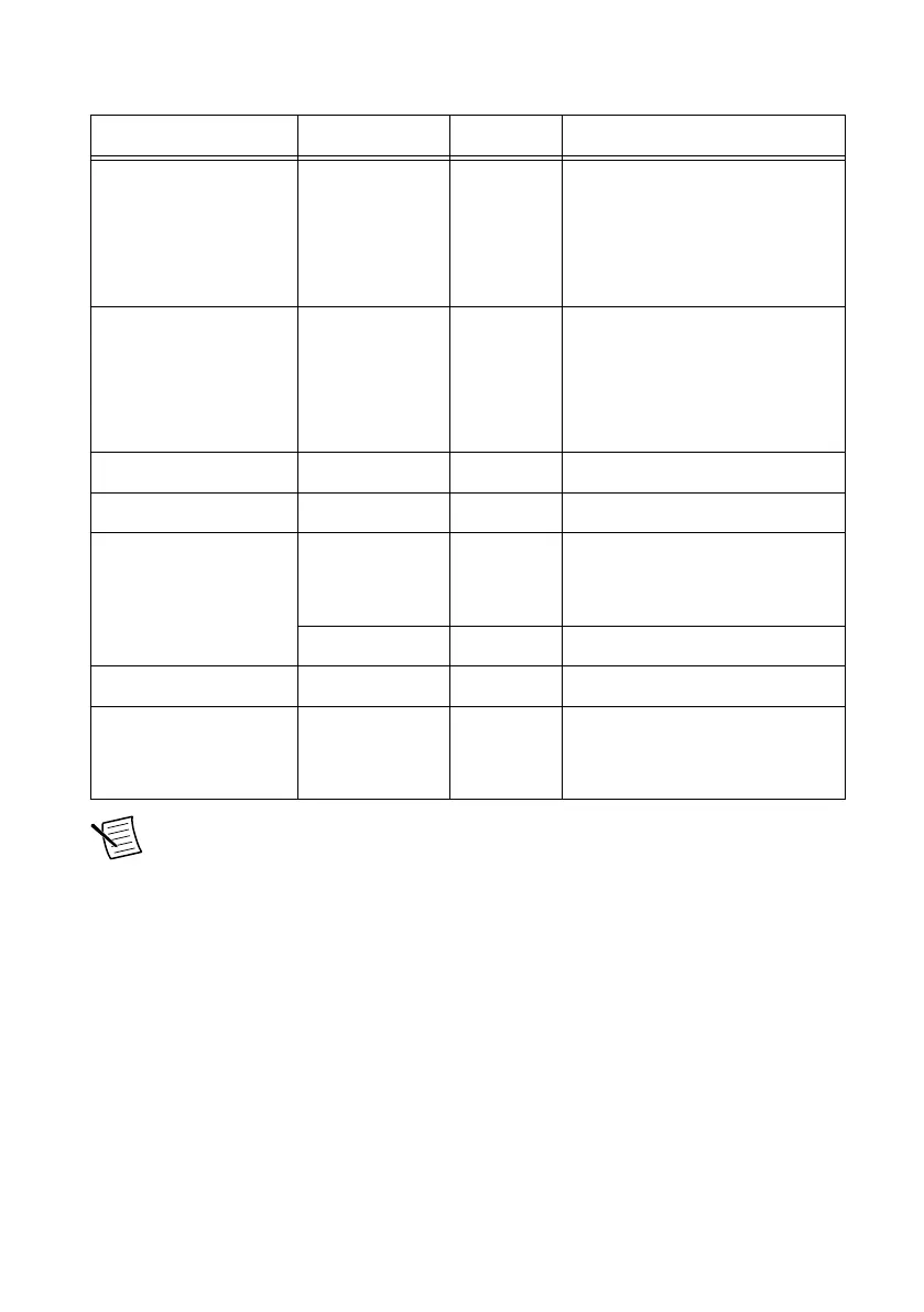
Table 1. PXIe-6570 Digital Data and Control Connector Pins
Pins Signal Name Signal Type Signal Description
1, 3, 5, 7, 9, 11, 13, 15,
17, 19, 21, 23, 25, 27,
29, 31, 35, 37, 39, 41,
43, 45, 47, 49, 51, 53,
55, 57, 59, 61, 63, 65
DIO <0..31> Data Bidirectional PPMU-capable
digital I/O data channels 0
through 31.
2, 4, 6, 8, 10, 12, 14, 16,
18, 20, 22, 24, 28, 32,
34, 36, 38, 40, 42, 44,
46, 48, 50, 52, 54, 56,
58, 62, 66, 68
GND Ground Instrument ground. Also default
ground reference if DUT Ground
Sense (DGS) is not connected.
26 CAL MEASURE Analog Resource for external calibration.
33 CAL SENSE Analog Resource for external calibration.
64 DGS Ground Optional DGS for improved
accuracy at higher currents in
some configurations.
CAL GND Analog Resource for external calibration.
67 CAL FORCE Analog Resource for external calibration.
30, 60 RESERVED N/A These terminals are reserved for
future use. Do not connect to
these pins.
Note The 32 digital I/O data channels on the digital pattern instrument are split
into banks for PPMU operation efficiency: DIO<0..7>, DIO<8..15>, DIO<16..23>,
DIO<24..31>. PPMU measurements run in parallel when you take measurements on
channels in different banks.
LED Status Indicators
Status indicators on the front panel of the PXIe-6570 provide feedback about instrument
operation.
Use the following table to determine the PXIe-6570 state using the Access LED status
indicator.
8 | ni.com | PXIe-6570 Getting Started Guide
 Loading...