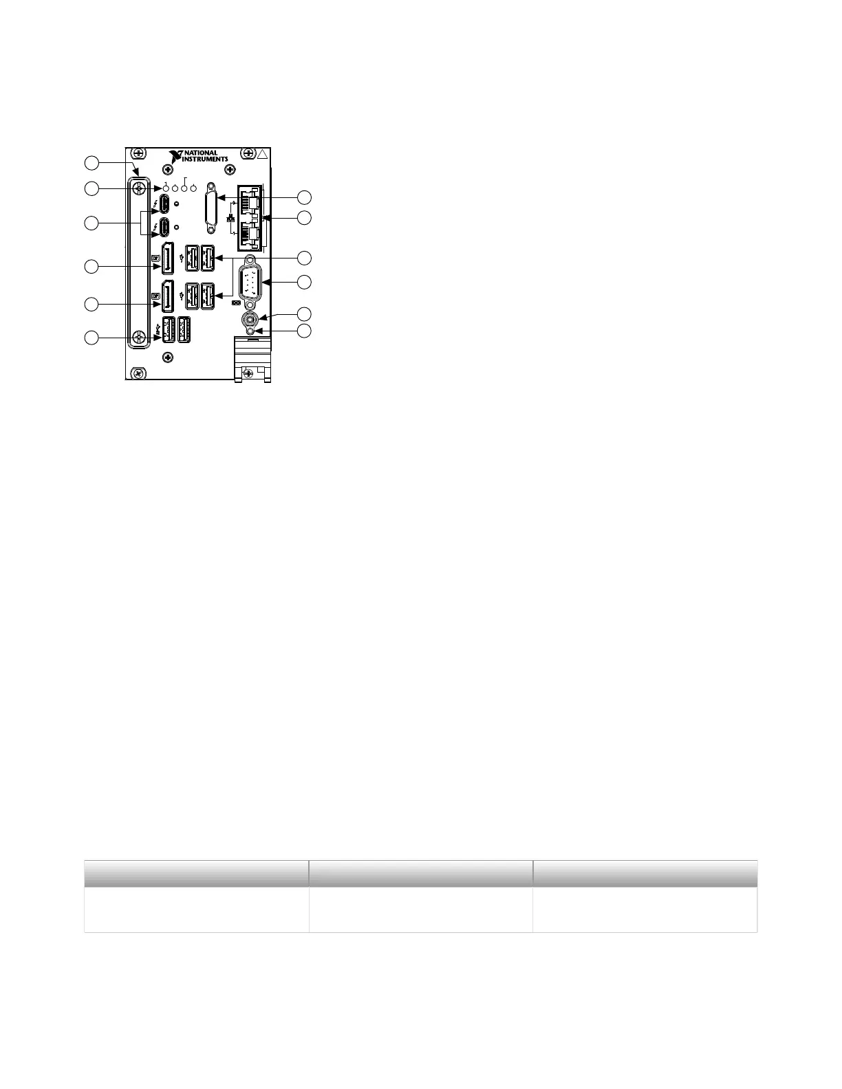
Figure 3. PXIe-8861 Front Panel Layout
PXIe-8861
Embedded Controller
TRIG
RESET
GPIB
DRIVE
PWR OK/
FAULT
USER1
USER2
ACT/
LINK
Pulse
10/100
/1000
2
1
2
4
5
7
1
3
10
11
6
8
9
12
1.
GPIB
2.
Ethernet
3.
USB 2.0
4.
RS-232 Serial
5. Trigger
6. Reset Button
7. USB 3.0
8.
DisplayPort 1.1
9. DisplayPort 1.2
10. Thunderbolt
11. LEDs
12.
Removable Hard Drive Shuttle (Removable Hard Drive Variant Only)
Front Panel Connectors
The following table lists various peripherals and their corresponding PXIe-8861
external connectors, bus interfaces, and functions.
Peripheral External Connector Description
Video (DisplayPort 1.1 and 1.2) DisplayPort ATI Radeon E6465 Embedded
GPU
© National Instruments
7
PXIe-8861 Getting Started Guide

 Loading...