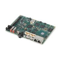
Figure 7. USB Connector Location
PXIe-8861
Embedded Controller
TRIG
RESET
GPIB
DRIVE
PWR OK/
FAULT
USER1
USER2
ACT/
LINK
Pulse
10/100
/1000
USB 2.0
4
1
9
5
4
1
USB 3.0
1.2
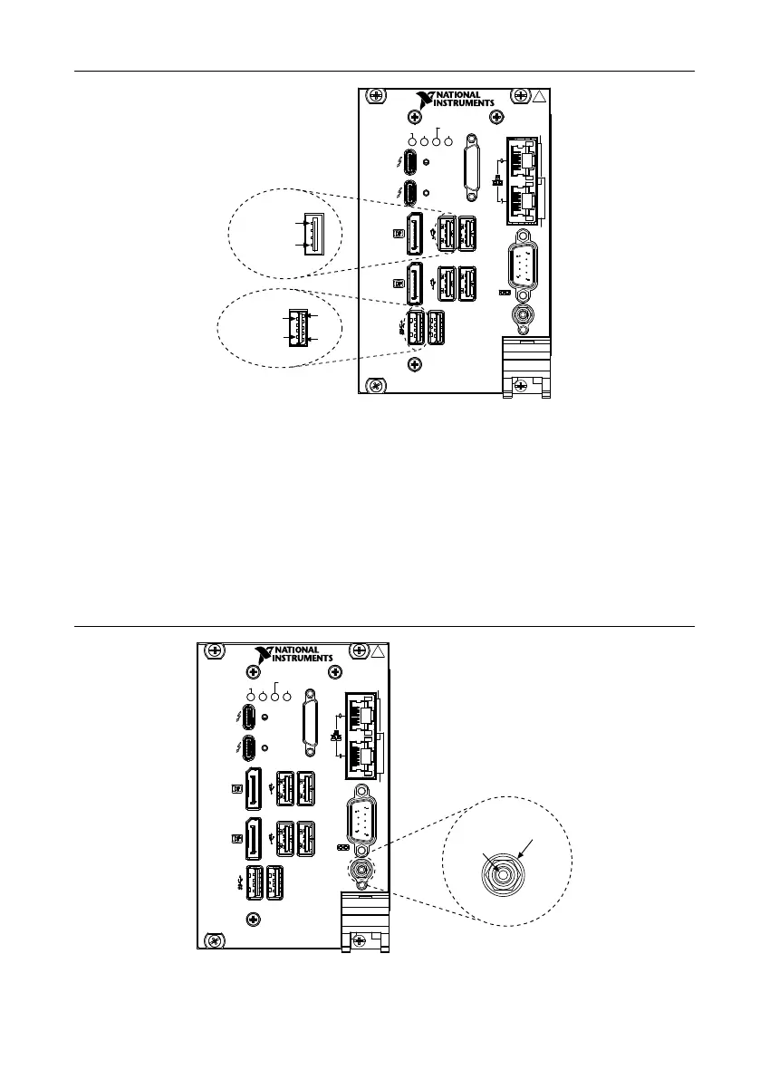
Trigger
The TRIG connector is the software-controlled trigger connection for routing PXI triggers to
or from the backplane trigger bus.
The following figure shows the TRIG connector location on the PXIe-8861.
Refer to PXI Trigger Connectivity in the PXIe-8861 Getting Started Guide for more
information about the SMB trigger.
Figure 8. TRIG Connector Location and Pinout
PXIe-8861
Embedded Controller
TRIG
RESET
GPIB
DRIVE
PWR OK/
FAULT
USER1
USER2
ACT/
LINK
Pulse
10/100
/1000
1
2
1.2
20 | ni.com | PXIe-8861 User Manual
 Loading...