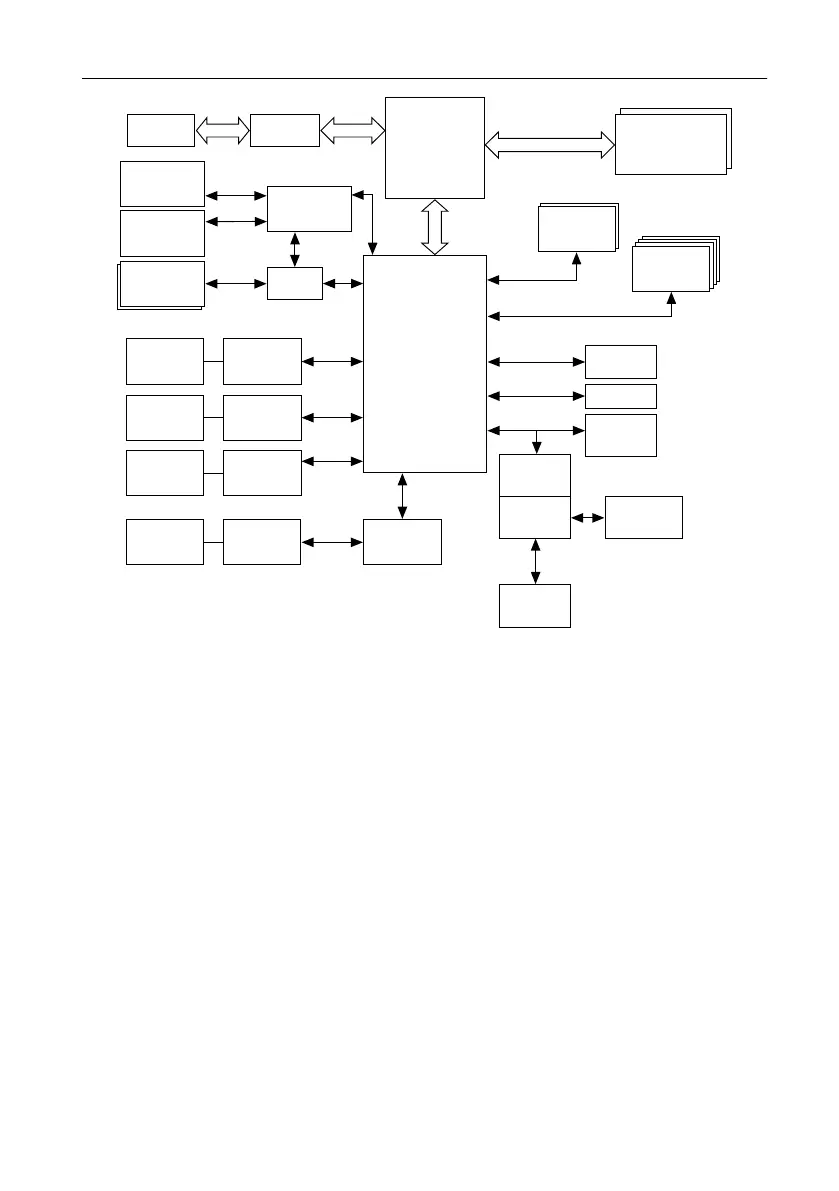
Figure 1. PXIe-8861 Block Diagram
Intel
C230 Series
Chipset
CPU
Intel Xeon
E3-1515M v5
SO-DIMM
DDR4-2133
DisplayPort 1.1
x2
USB 2.0
M.2 SSD
FLASH BIOS
Watchdog
Trigger
SMB
Connector
TPM
x16
PXI
Triggers
x4
Intel I219
Gigabit
PHY
RJ45
Port 0
PCI Express
PCI Express
Switch
PXI
Express
4x4
or 2x8
USB 3.0
x2
GPU
AMD Radeon
E6465
Thunderbolt 3
x2
DSL 6540
Intel I210
Gigabit
PHY
RJ45
Port 1
GPIB
Controller
GPIB
Connector
PCI Express-
to-PCI Bridge
DisplayPort 1.2
RS232
UART
The PXIe-8861 consists of the following logic blocks on one circuit card assembly (CCA):
• The processor is an Intel
®
Xeon
®
E3-1515M v5 processor (Quad Core, 2.8 GHz base,
3.7 GHz turbo frequency).
• The SO-DIMM block consists of two DDR4 PC-2133 SO-DIMM sockets that can hold up
to 32 GB of memory.
• The processor provides the PCI Express interface to the PXI Express backplane through a
PCI Express switch.
• The Platform Controller Hub (PCH) provides the USB, PCI Express x1, and LPC
interfaces that connect to the peripherals on the PXIe-8861.
• The DisplayPort 1.1 block consists of a 1.1 compatible DisplayPort connector nearest the
USB 3.0 ports.
• The DisplayPort 1.2 block consists of a 1.2 compatible DisplayPort connector nearest the
Thunderbolt 3 connectors.
• The USB block consists of two Hi-Speed USB 2.0 connectors and two SuperSpeed USB
3.0 connectors.
• The Ethernet Port 0 block consists of an Intel
®
I219 Gigabit Ethernet Connection.
• The Ethernet Port 1 block consists of an Intel
®
I210 Gigabit Ethernet Connection.
4 | ni.com | PXIe-8861 User Manual

 Loading...