B-6 | ni.com
Appendix B Hardware Configuration
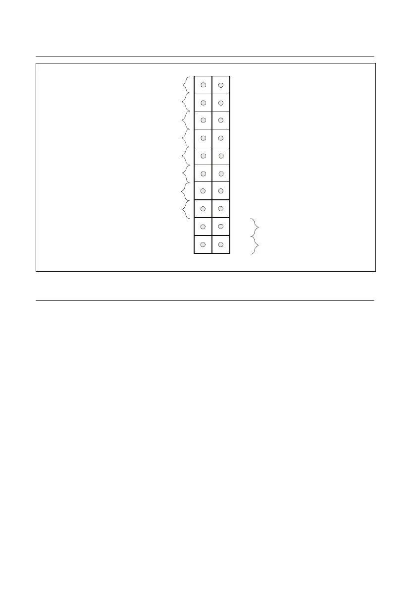
Figure B-2. JF1 Header Pins
Motherboard Connections
This section describes the connections on the motherboard and provides pinout definitions.
Note that depending on how the system is configured, not all connections are required. The
LEDs on the motherboard are also described here. A severboard layout indicating component
locations may be found in Appendix B.
Refer to the Safety Information section of Chapter 2, Hardware Configuration, before installing
or removing components.
Power Connections
Two power connections on the motherboard must be connected to the power supply. The wiring
is included with the power supply.
• 24-pin Primary ATX Power (JPW1)
• 8-pin Processor Power (JPW2)
• CMOS Battery Power (J18)
ATX Main Power Connector
The primary power connector (JPW1) meets the ATX SSI EPS 12 V specification. You must
also connect the 8-pin (JPW2) processor power connector to your power supply.
Power Button
OH/Fan Fail LED
1
NIC1 Link LED
Reset Button
2
Power Fail LED
HDD LED
FP PWRLED
Reset
PWR
3.3V Stby
3.3V Stby
UID LED Blue Cathode
Ground
Ground
1920
3.3V
X
Ground
NMI
X
NIC2 Link LED
NIC2 Activity LED
NIC1 Activity LED

 Loading...