NI USB-6001/6002/6003 User Guide | © National Instruments | 9
Pinout and Signal Descriptions
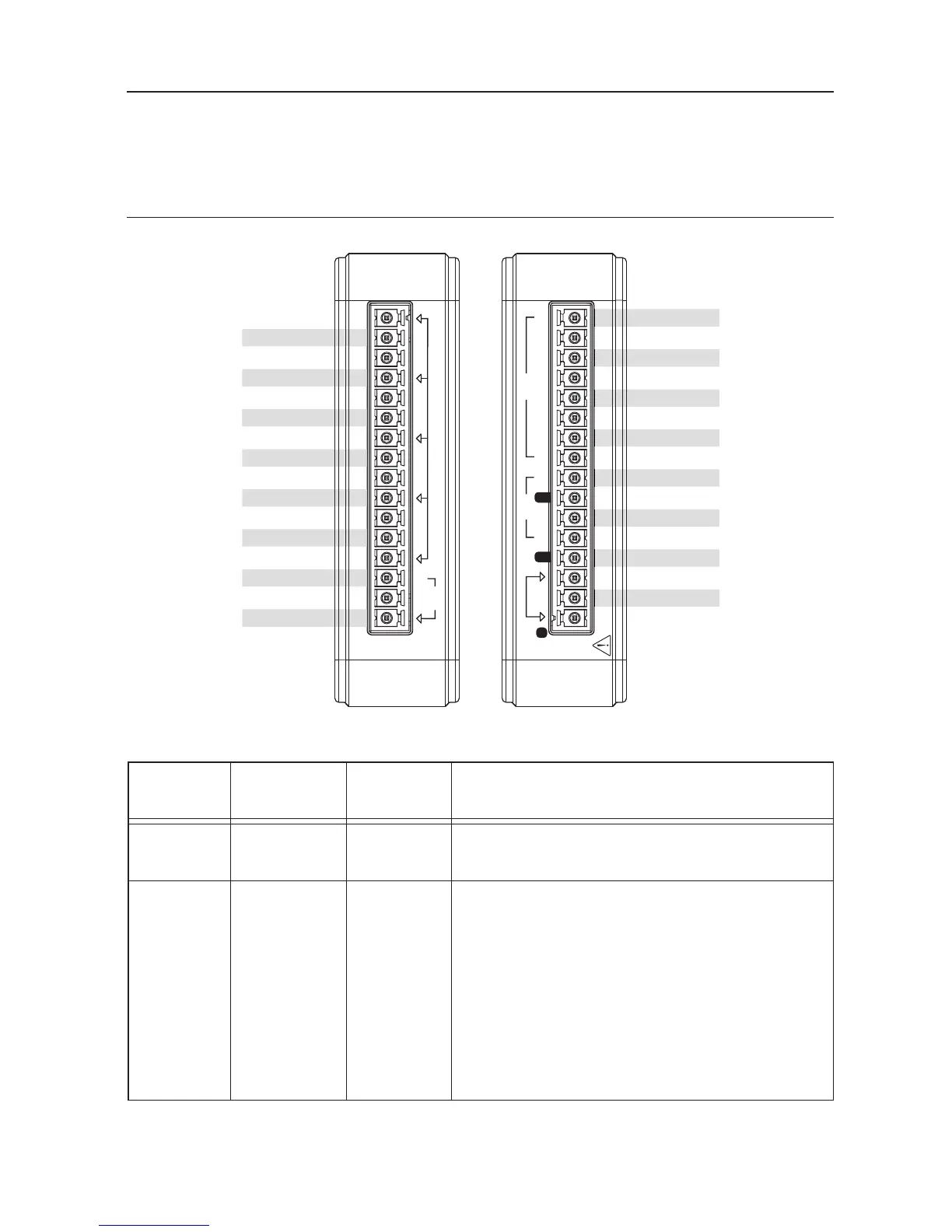
Figure 4 shows the NI DAQ device pinout. Analog input signal names are listed as single-ended
analog input name, AI x, and then the differential analog input name, (AI x+/-). Refer to Table 5
for a detailed description of each signal.
Figure 4. NI USB-6001/6002/6003 Pinout
Table 5. Signal Descriptions
Signal
Name Reference Direction Description
AI GND — — Analog Input Ground—The reference point
for single-ended analog input measurements.
AI <0..7> AI GND Input Analog Input Channels 0 to 7—For
single-ended measurements, each signal
corresponds to one analog input voltage channel.
For differential measurements, AI 0 and AI 4 are
the positive and negative inputs of differential
analog input channel 0. The following signal
pairs also form differential input channels:
AI <1,5>, AI <2, 6>, and AI <3, 7>. Refer to the
Analog Input section for more information.