NI Digital System Development Board User Manual | © National Instruments | 31
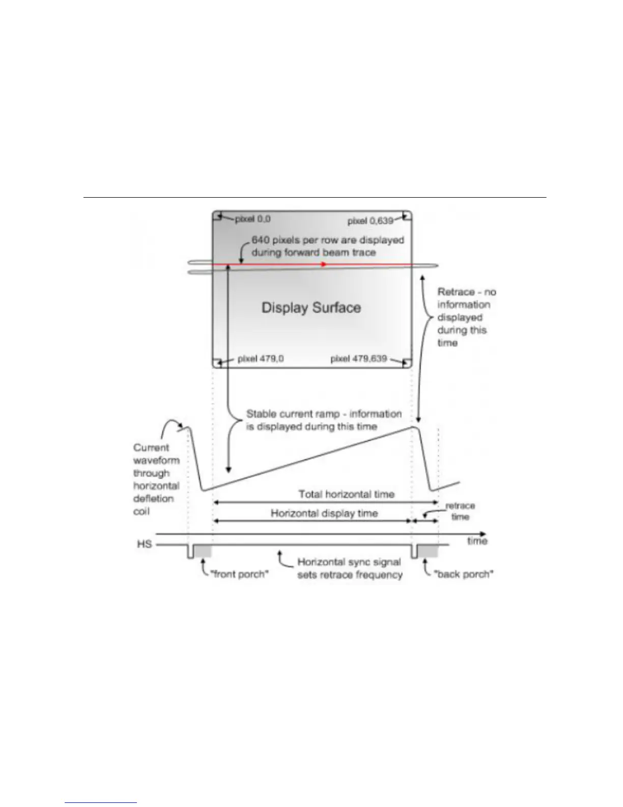
Modern VGA displays can accommodate different resolutions, and a VGA controller circuit
dictates the resolution by producing timing signals to control the raster patterns. The controller
must produce synchronizing pulses at 3.3 V (or 5 V) to set the frequency at which current flows
through the deflection coils, and it must ensure that video data is applied to the electron guns at
the correct time. Raster video displays define a number of rows that corresponds to the number
of horizontal passes the cathode makes over the display area, and a number of columns that
corresponds to an area on each row that is assigned to one picture element, or pixel. Typical
displays use from 240 to 1200 rows and from 320 to 1600 columns. The overall size of a display
and the number of rows and columns determines the size of each pixel.
Figure 11. VGA Horizontal Synchronization
Video data typically comes from a video refresh memory; with one or more bytes assigned to
each pixel location (the DSDB uses 16 bits per pixel). The controller must index into video
memory as the beams move across the display, and retrieve and apply video data to the display
at precisely the time the electron beam is moving across a given pixel.
A VGA controller circuit must generate the HS and VS timings signals and coordinate the
delivery of video data based on the pixel clock. The pixel clock defines the time available to
display one pixel of information. The VS signal defines the refresh frequency of the display, or
the frequency at which all information on the display is redrawn. The minimum refresh
 Loading...