34 | ni.com | NI Digital System Development Board User Manual
DSDB, as it might result in back-powering the board through the termination resistors.
Resolutions up to 720p (1280 × 720) have been tested.
HDMI and DVI are high-speed source-synchronous serial protocols. Implementations on FPGA
are required to use certain built-in primitives to properly synthesize the correct clock frequency,
serialize the transmission, and keep a lock on the signal. The actual implementation of the
HDMI/DVI protocols is outside the scope of this manual. Vivado IP cores are available for free
from www.github/digilent that can be used to handle this. These IP cores convert the high-speed
serial data to an RGB interface that is very similar to the one used to communicate with a VGA
port.
Touchscreen Display
The DSDB has a TFT-LCD with a capacitive touch panel mounted on the LCD. The LCD is a
5” diagonal, 800 x 480 RGB display with a 24-bit color depth. The touch panel size has been
scaled to the LCD so that every point read from the touch panel can be converted to a RGB pixel
on the TFT-LCD. Although the LCD and touch panel come as an assembly, they have
independent controllers and are driven separately.
LCD Display
The LCD has an ILI6122 timing controller mounted on it which interfaces to the TFT display.
The user has access only to certain pins of the controller, specifically those which are used to
send data to the LCD. In order to access the controller pins the LCD uses a strip connector with
the following pin-out.
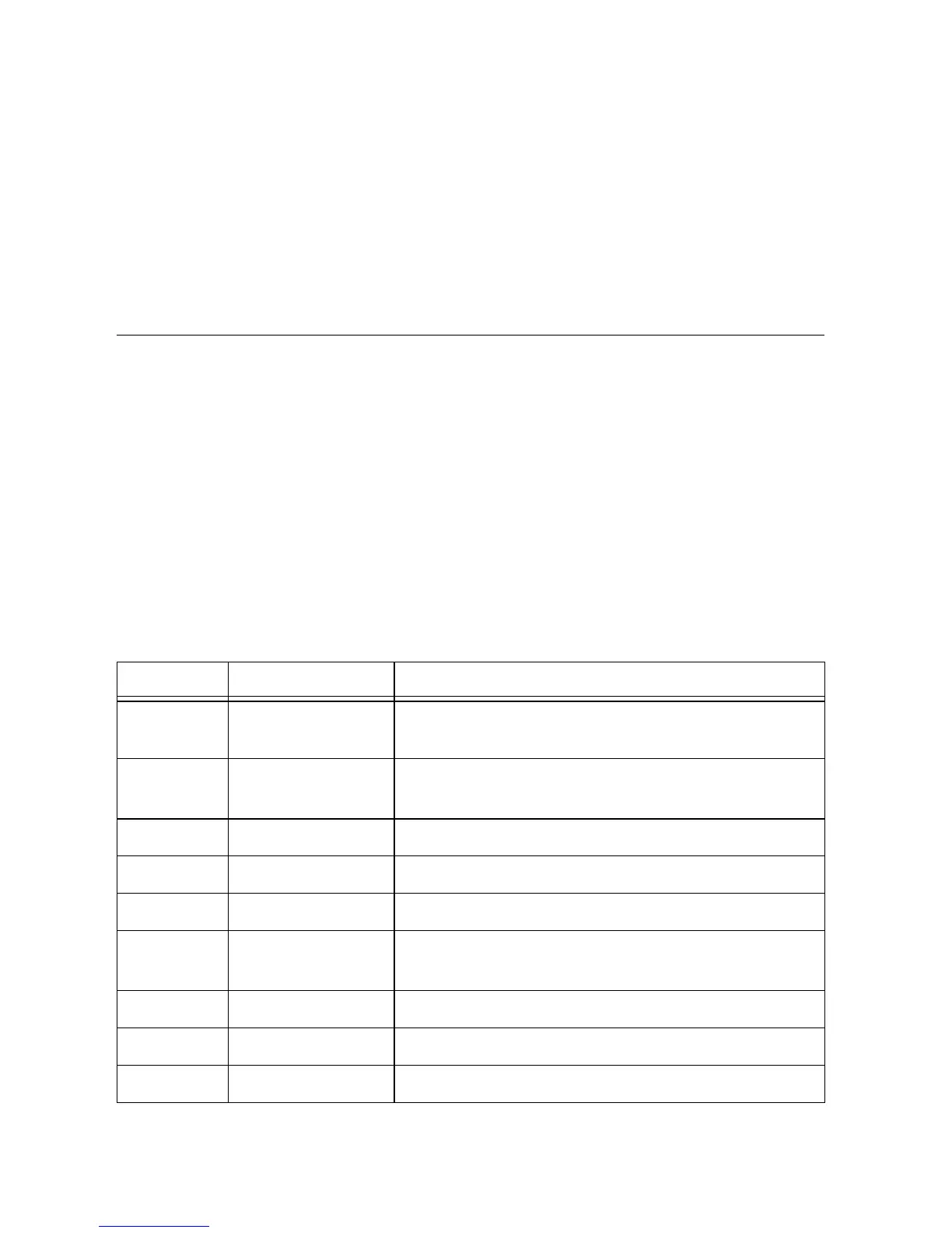
Table 15. LCD Control Signals
Pin Signal Description
1 BCK_LED_K Back-light LED cathode. Connected to the FP6745
LED driver
2 BCK_LED_A Back-light LED anode. Connected to the FP6745 LED
driver
3 GND Ground
4 VCC 3.3 V
5 - 12 TFT_R0 - TFT_R7 8-bit data bus corresponding to the red signal.
13 - 20 TFT_G0 -
TFT_G7
8-bit data bus corresponding to the green signal.
21 - 28 TFT_B0 - TFT_B7 8-bit data bus corresponding to the blue signal.
29 GND Ground
30 TFT_DCLK Data clock
 Loading...