NI Digital System Development Board User Manual | © National Instruments | 35
In order to facilitate the dimming of the back-light on the LCD, the FP6745 LED driver has been
used. The user has direct access to the enable pin of the LED-driver; by driving this pin with a
PWM signal the user will obtain a variety of back-light intensities dependent on the duty cycle
of the PWM signal. When driving the back-light with PWM, it is highly recommended to choose
a PWM frequency above 20 kHz, because this circuit may interfere with the audio circuit. Before
starting to use the LCD, the DISP pin must be set to logic high. This pin is an enable pin which
allows the user to turn off the display without interrupting the timing and data flow. When
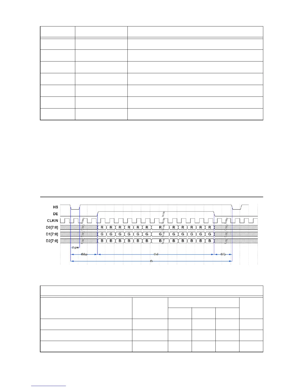
sending data to the display, the following timing specifications must be respected:
Figure 14. Horizontal Timing
31 TFT_DISP Display enable, active high
32 TFT_HS Horizontal synchronisation pulse
33 TFT_VS Vertical synchronisation pulse
34 TFT_DE Active video signal
35 NC Not connected
36 GND Ground
37 - 40 NC Not connected
Table 16. Horizontal Timing
Horizontal Input Timing
Parameter Symbol Val ue Unit
Min. Typ. Max.
Active Area thd — 800 — CLKIN
CLKIN frequency fclk — 33.3 50 MHz
Horizontal line period th 862 1056 1200 CLKIN
Table 15. LCD Control Signals (Continued)
Pin Signal Description
 Loading...